MIPI DSI Display Integration Guide for Compact Embedded Devices
An engineering guide to MIPI DSI display integration, covering lane count, initialization commands, FPC length, signal integrity, Linux device trees, power sequencing, and validation.
Selecting a display for handheld terminals, smart home panels, compact medical devices, wearables, and battery-powered industrial controllers is rarely a one-variable decision. This guide focuses on using MIPI DSI displays in compact embedded devices without underestimating software and signal-integrity work from an engineering point of view: optical behavior, electrical integration, mechanical stack-up, validation, supply risk, and field reliability.
MIPI DSI looks attractive because it uses few pins and low power, but it is less forgiving than older parallel or LVDS interfaces when cable length, initialization, or driver support is weak. Projects often stall when the panel lights up but shows no image, works only with a vendor demo image, or fails intermittently after the FPC is extended to fit the enclosure.
The practical recommendation is simple: Choose MIPI DSI when the display is close to the processor and the software stack can support the exact panel IC. The detailed work is in proving that decision against the real product environment, not against a marketing image or an isolated datasheet value.
1. Decision Summary
| Design area | Engineering implication | Practical note |
|---|---|---|
| Pin count | Low | Good for compact products |
| Cable reach | Short | FPC layout must be controlled |
| Power | Efficient | Good for battery systems |
| Software | Panel-specific | Initialization commands matter |
| Industrial noise | Manageable | Needs shielding and layout care |
The table should not be used as a replacement for qualification testing. It is a way to focus the first design review. In a real project, the display decision should involve electrical engineering, mechanical engineering, firmware, industrial design, purchasing, quality, and the supplier application team. Each group sees a different failure mode: signal margin, enclosure tolerance, boot timing, touch feel, lifecycle risk, or cosmetic yield.
2. Lane Count and Bandwidth
A MIPI DSI link uses one or more high-speed data lanes plus a clock lane. The required lane count depends on resolution, refresh rate, color depth, blanking, and protocol overhead. Do not assume that a four-lane display can be driven by a two-lane host, even if the connector can be adapted. Calculate the pixel bandwidth and confirm the host, panel, and driver mode all support the same configuration.
3. Initialization and Panel Drivers
Many MIPI panels require command sequences to configure power, gamma, timing, inversion, and sleep modes. These commands may come from the panel vendor, the driver IC vendor, or a reference design. In Linux systems, the device tree and panel driver must match the physical display. A generic driver may bring up the link but leave color, orientation, brightness, or sleep behavior incorrect.
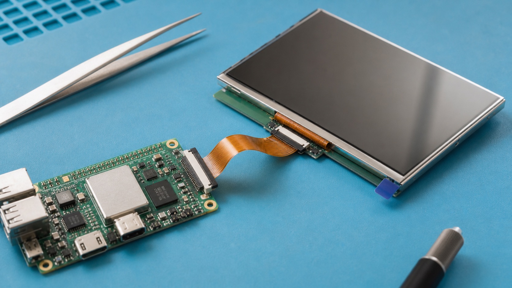
4. FPC Length and Signal Integrity
MIPI DSI is designed for short internal connections. Long or poorly routed FPC cables increase insertion loss, crosstalk, and EMI risk. Keep the panel close to the processor when possible. If the mechanical design forces distance, involve hardware engineers early and validate with the final cable, connector, grounding, and enclosure. Avoid treating MIPI like HDMI or LVDS; the margin is different.
5. Power States and User Experience
Compact devices often use aggressive sleep and wake behavior. The display must handle suspend, resume, backlight ramping, touch wake, and error recovery. A product that boots correctly once may still fail after repeated sleep cycles. Define display state transitions and test them alongside battery management and thermal throttling.
6. Validation Plan
A credible validation plan should use the final display stack, not an open-frame sample sitting on a desk. Build at least one sample with the intended cover lens, touch sensor, bonding method, cable, connector, backlight driver, enclosure, gasket, and firmware. Then test the conditions that match the product: operating temperature, storage temperature, vibration if relevant, ESD, EMI, repeated power cycling, brightness changes, sleep and resume, and long-duration operation.
For optical decisions, inspect the display under the lighting that customers will actually see. For electrical decisions, test with production cable length and realistic grounding. For mechanical decisions, measure tolerance stack-up and assembly repeatability. For software decisions, confirm boot behavior, error recovery, orientation, dimming, and touch calibration. A display that passes a one-hour bench test can still fail when installed in a sealed enclosure, driven at full brightness, or used by an operator wearing gloves.
7. Procurement and Lifecycle Review
Engineering teams should ask suppliers for more than a quotation. Useful documentation includes the LCD datasheet, module drawing, interface timing, backlight electrical data, optical test method, reliability report, RoHS and REACH status if required, packaging specification, PCN policy, and expected lifecycle. If the product is planned for long-term production, identify whether the panel, driver IC, touch controller, LED, polarizer, and adhesive are stable parts or subject to frequent substitution.
Second sources should be considered early. Even when a perfect drop-in alternate does not exist, knowing the nearest replacement helps the team preserve mechanical space, interface flexibility, and firmware options. A display can become a single point of failure for the whole product if the team treats it as a commodity part.
8. Engineering Checklist
- Confirm lane count, data rate, color depth, and refresh target.
- Obtain the exact initialization sequence for the panel and driver IC.
- Test with the production FPC length and bend radius.
- Validate suspend, resume, rotation, brightness, and ESD recovery.
9. Final Recommendation
For embedded and industrial products, the best display choice is the one that remains readable, electrically stable, manufacturable, and available throughout the product lifecycle. Do not approve a display from a single specification or a clean-room demo photo. Approve it after the optical stack, interface, touch behavior, thermal path, firmware, and supplier controls have been reviewed together.
That approach takes more effort during design, but it reduces late redesigns, field complaints, and supply surprises. It is also the difference between a display that simply turns on and a display subsystem that supports the product reliably for years.
Related Engineering Context
If the project is still in mechanical planning, read display interface decisions before enclosure design before selecting the processor and panel. For higher-resolution embedded systems where MIPI margin becomes tight, the eDP display panel guide may be the more appropriate next step.