LVDS Display Panel Design Guide for Industrial HMIs
A practical guide to using LVDS display panels in industrial systems, including cable design, mapping, EMI control, power sequencing, resolution limits, and validation tests.
Selecting a display for machine controllers, medical terminals, vehicle displays, rugged tablets, and long-life embedded monitors is rarely a one-variable decision. This guide focuses on integrating LVDS TFT panels into robust industrial HMI products from an engineering point of view: optical behavior, electrical integration, mechanical stack-up, validation, supply risk, and field reliability.
LVDS is mature and reliable, but integration mistakes still cause flicker, color swap, intermittent boot failures, and electromagnetic compatibility problems. The typical issue is not the LVDS standard itself. It is mismatched bit mapping, poor cable impedance, weak grounding, incorrect power sequence, or a software timing mode copied from a similar but not identical panel.
The practical recommendation is simple: Use LVDS when robustness and cable reach matter, but control the electrical details from the first schematic review. The detailed work is in proving that decision against the real product environment, not against a marketing image or an isolated datasheet value.
1. Decision Summary
| Design area | Engineering implication | Practical note |
|---|---|---|
| Cable length | Better than MIPI and eDP | Still needs impedance control |
| EMI behavior | Good differential signaling | Layout and shielding still matter |
| Resolution | Excellent up to common industrial HD sizes | May need dual channel for high pixel clocks |
| Software | Simple timing model | Mapping and bit depth must match |
| Lifecycle | Strong industrial support | Older platforms may vary in pinout |
The table should not be used as a replacement for qualification testing. It is a way to focus the first design review. In a real project, the display decision should involve electrical engineering, mechanical engineering, firmware, industrial design, purchasing, quality, and the supplier application team. Each group sees a different failure mode: signal margin, enclosure tolerance, boot timing, touch feel, lifecycle risk, or cosmetic yield.
2. Panel Timing and Mapping
LVDS panels are not interchangeable just because the connector has the same pin count. Check resolution, pixel clock, horizontal and vertical porch values, sync polarity, color depth, and JEIDA or VESA mapping. A mismatch can show as wrong colors, unstable images, or no image at all. Keep the exact panel datasheet and timing parameters under revision control so firmware and hardware teams use the same source.
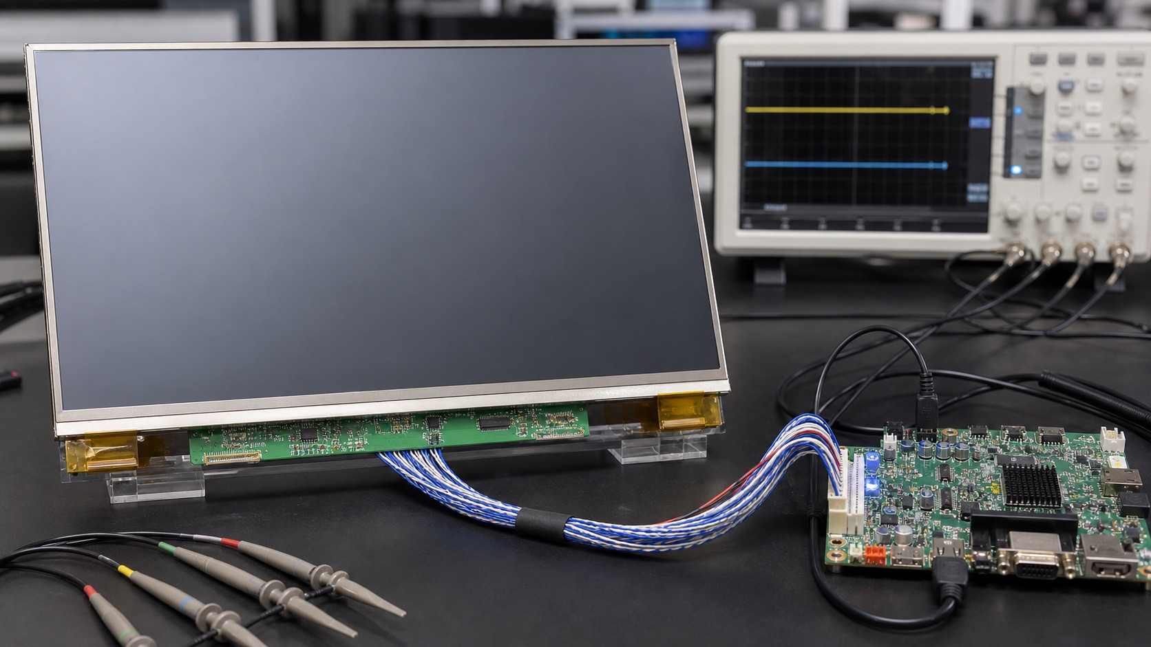
3. Cable and Connector Design
Differential pairs should maintain controlled impedance and matched length. Avoid running LVDS near noisy power switching nodes, motor lines, or high-current LED backlight traces. For longer cables, use proper shielding, strain relief, and connector retention. A display that works on a short bench cable may fail when installed in a metal enclosure with a moving harness.
4. Grounding and EMI
LVDS reduces common-mode noise, but it does not remove the need for careful grounding. Decide whether the cable shield bonds to chassis at one or both ends based on the product architecture and EMC test plan. Provide a clean return path and avoid ground discontinuities under the transmitter. Common-mode chokes can help in some designs, but they should be selected and validated rather than added blindly.
5. Power Sequencing and Backlight Control
Many LVDS panels require panel logic power, reset, LVDS data, and backlight enable to follow a defined order. Violating this sequence can cause white flash, latch-up risk, or intermittent startup. The backlight driver may also need soft-start and fault handling. Treat the display as a subsystem with logic, data, backlight, touch, and mechanical connections, not just a video cable.
6. Validation Plan
A credible validation plan should use the final display stack, not an open-frame sample sitting on a desk. Build at least one sample with the intended cover lens, touch sensor, bonding method, cable, connector, backlight driver, enclosure, gasket, and firmware. Then test the conditions that match the product: operating temperature, storage temperature, vibration if relevant, ESD, EMI, repeated power cycling, brightness changes, sleep and resume, and long-duration operation.
For optical decisions, inspect the display under the lighting that customers will actually see. For electrical decisions, test with production cable length and realistic grounding. For mechanical decisions, measure tolerance stack-up and assembly repeatability. For software decisions, confirm boot behavior, error recovery, orientation, dimming, and touch calibration. A display that passes a one-hour bench test can still fail when installed in a sealed enclosure, driven at full brightness, or used by an operator wearing gloves.
7. Procurement and Lifecycle Review
Engineering teams should ask suppliers for more than a quotation. Useful documentation includes the LCD datasheet, module drawing, interface timing, backlight electrical data, optical test method, reliability report, RoHS and REACH status if required, packaging specification, PCN policy, and expected lifecycle. If the product is planned for long-term production, identify whether the panel, driver IC, touch controller, LED, polarizer, and adhesive are stable parts or subject to frequent substitution.
Second sources should be considered early. Even when a perfect drop-in alternate does not exist, knowing the nearest replacement helps the team preserve mechanical space, interface flexibility, and firmware options. A display can become a single point of failure for the whole product if the team treats it as a commodity part.
8. Engineering Checklist
- Verify JEIDA/VESA mapping and bit depth with the exact panel.
- Review cable impedance, pair skew, shielding, and connector retention.
- Validate cold start, hot start, brownout, and backlight enable timing.
- Run EMI pre-scan with production cable length and enclosure.
9. Final Recommendation
For embedded and industrial products, the best display choice is the one that remains readable, electrically stable, manufacturable, and available throughout the product lifecycle. Do not approve a display from a single specification or a clean-room demo photo. Approve it after the optical stack, interface, touch behavior, thermal path, firmware, and supplier controls have been reviewed together.
That approach takes more effort during design, but it reduces late redesigns, field complaints, and supply surprises. It is also the difference between a display that simply turns on and a display subsystem that supports the product reliably for years.
Related Engineering Context
For a broader comparison against MIPI DSI, eDP, and HDMI, use the main display interfaces guide as the architecture-level reference. If the enclosure layout is still being developed, the blog on display interface decisions before enclosure design explains why cable routing should be reviewed early.