How to Read a TFT LCD Datasheet: An Engineer's Guide
Learn how to read a TFT LCD datasheet, verify optical and electrical specs, catch integration risks, and build a practical panel approval checklist.
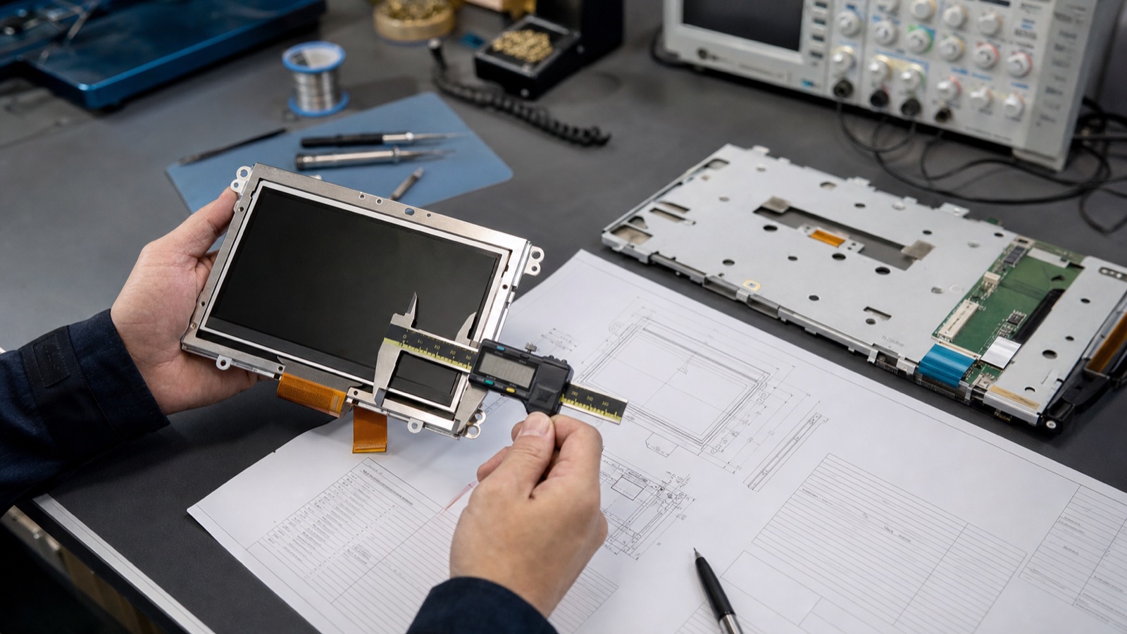
A TFT LCD datasheet can look reassuringly precise. It may list an exact outline, a neat timing table, a 1000:1 contrast ratio, and an operating range down to -20°C. None of those numbers is useful, however, until you know the conditions behind it and whether the value is guaranteed, typical, or merely descriptive.
The safest way to read an LCD datasheet is not from page one to the end. Read it in the order that the display can hurt the project: part identity, mechanical fit, electrical limits, interface timing, backlight load, optical performance, environmental qualification, and change control. That sequence catches expensive problems before a good-looking sample earns an early approval.
This guide is written for embedded and industrial display projects, but the method also works for medical instruments, charging equipment, test systems, smart controls, and outdoor terminals.
Start with the exact part number and document revision
Before reviewing performance, confirm what the document actually covers. LCD families often contain variants that share a size and resolution but differ in interface, brightness, polarizer, FPC shape, touch option, or operating temperature.
Record these items at the top of the review sheet:
- Full manufacturer and module part number, including every suffix.
- Datasheet revision and release date.
- Sample label, lot code, and firmware or initialization version if applicable.
- Whether the document describes the LCD panel, a complete display module, or a panel-plus-touch assembly.
- Any supplier-added backlight, interface board, touch controller, cover lens, or optical bonding.
A supplier quotation that says “7-inch IPS, 1024×600, LVDS” is not a controlled specification. Two modules can match that description and still have different connector pinouts, mounting tabs, LED strings, timing limits, or polarizer orientation. Approval should follow the orderable part number, not the sales description.
Read the mechanical drawing before the optical table
Mechanical incompatibility is one of the least negotiable display problems. Firmware can sometimes compensate for timing or orientation. An enclosure tool cannot easily compensate for a misplaced FPC or a bezel pressing on the active area.
Check the drawing for more than overall length, width, and thickness:
| Drawing item | Why it matters |
|---|---|
| Active area | The illuminated pixel area; use it to align the UI and viewing window |
| Viewing area | The opening the supplier expects to remain visible; it may differ from the active area |
| Module outline | The metal frame, PCB, tape, and protrusions that must clear the enclosure |
| Datum and tolerances | Determines whether the display can be assembled repeatedly, not just once |
| FPC exit and connector side | Affects bend radius, PCB placement, service access, and cable strain |
| Keep-out zones | Protects driver ICs, components, bonded areas, and sensitive frame regions |
| Recommended bezel opening | Helps prevent clipping, light leakage, and pressure on the LCD cell |
| Center of active area | May not be the same as the center of the module outline |
Do not scale a PDF drawing and measure it on screen. Use the stated dimensions. If the drawing lacks tolerances, request them. A nominal thickness without a maximum value is not enough to design a gasket stack or a bonded cover lens.
Also ask whether the drawing represents a bare LCD or the delivered assembly. Optical bonding, double-sided tape, a touch sensor, and a cover lens change thickness, flatness, cable location, and tolerance accumulation.
Separate absolute maximum ratings from operating conditions
Electrical tables commonly include both absolute maximum ratings and recommended operating conditions. They are not interchangeable.
An absolute maximum is a damage boundary, not a design target. If a logic supply has an absolute maximum of 3.6 V, that does not mean 3.6 V is an acceptable continuous rail. The operating table may specify 3.3 V nominal with a much narrower allowed range. Design to the operating range and leave margin for regulator tolerance, ripple, startup overshoot, cable loss, and temperature.
Review every rail and signal group:
- Logic or panel supply voltage and current.
- I/O voltage level and whether inputs are tolerant before the main rail is present.
- Analog LCD rails if they are generated externally.
- LED forward voltage, string arrangement, and backlight current.
- Reset, standby, enable, and backlight control pins.
- Input-high, input-low, and leakage limits.
- Power-on, power-off, and signal-before-power restrictions.
Current figures deserve special attention. A “typical” current may be measured with a particular test pattern, refresh rate, temperature, and backlight setting. Use maximum or characterized load where available. If only a typical figure is given, measure representative samples and size the supply with explicit margin.
Treat the pin table as a controlled interface
Connector type alone does not make two displays compatible. A 40-pin FPC can carry RGB, LVDS, MIPI DSI, power, touch, or a supplier-specific combination. Even two LVDS panels with the same connector can swap lane mapping, bit order, supply pins, or backlight control.
For the pin table, verify:
- Connector manufacturer and mating part number.
- Pin-one orientation as seen on the actual module.
- Supply and ground pin count.
- Signal voltage levels and termination requirements.
- Lane mapping, polarity, and pixel format.
- Reset, enable, panel-detect, and dimming behavior.
- Reserved or “do not connect” pins.
- Touch signals, if the touch assembly shares the same cable.
Mark every power pin and ground pin on a printed or reviewed schematic. Reversed connector drawings and top-view/bottom-view confusion cause surprisingly destructive mistakes. Before powering an unfamiliar module, confirm continuity from the mating connector to the intended rail.
If the project is still choosing between interfaces, the LVDS, MIPI, eDP, and HDMI comparison gives the system-level trade-offs. Once an interface is chosen, the panel-specific timing and mapping in the datasheet take priority over generic assumptions.
Decode the timing table instead of copying the typical row
Digital displays accept pixels inside a timing envelope. A typical timing may work on a bench, but production approval should use the minimum and maximum limits for pixel clock, horizontal total, vertical total, sync width, and porch values.
For a raster interface, use these relationships as a sanity check:
Horizontal total = active pixels + front porch + sync width + back porch
Vertical total   = active lines  + front porch + sync width + back porch
Frame rate       = pixel clock / (horizontal total × vertical total)
If the calculation does not match the stated refresh rate, stop and resolve the discrepancy. The datasheet may use a different mode, contain a typographical error, or assume a clock range rather than one fixed value.
Also confirm:
- Pixel sampling edge.
- HSYNC and VSYNC polarity.
- Data-enable mode versus sync mode.
- RGB versus BGR order.
- 18-bit versus 24-bit color mapping.
- LVDS JEIDA versus VESA mapping.
- MIPI DSI lane count, mode, packet format, and initialization commands.
- eDP lane rate, link training, AUX behavior, and backlight control.
For command-driven panels, the initialization sequence is part of the display specification even when it arrives as a separate file. Put that file under version control. A spreadsheet pasted into an email is not a durable firmware release process.
Read the backlight section as a power and thermal design input
The LCD cell does not create light. The LED backlight often consumes more power than the panel electronics and is usually the part most affected by high temperature and long duty cycles.
A useful backlight review includes:
- Number of LED strings and LEDs per string.
- Forward-voltage range at the specified current and temperature.
- Maximum continuous LED current.
- Connector and cable current rating.
- Dimming method, permitted PWM frequency, and minimum usable duty cycle.
- Backlight lifetime definition, test current, and LED temperature.
- Whether the driver is included in the module or must be designed on the main board.
Do not choose a boost converter from the typical forward voltage alone. The driver needs enough compliance voltage for the maximum string voltage, cold startup, component tolerance, and switching losses. It also needs open-string, short-circuit, overvoltage, and thermal behavior appropriate for the product.
For a high-brightness module, connect this review to enclosure temperature and duty cycle. The high-brightness TFT display selection guide explains why a backlight that reaches the target luminance at room temperature can still have poor lifetime margin in a sealed outdoor product.
Optical specifications need their test conditions
Optical numbers are especially easy to compare incorrectly. Look for the measurement method, instrument geometry, test pattern, backlight current, ambient temperature, warm-up time, and defined viewing direction.
| Specification | What to verify |
|---|---|
| Luminance | Minimum or typical; center point or multi-point average; backlight current; warm-up condition |
| Uniformity | Formula used; number and position of measurement points |
| Contrast ratio | White and black measured under the same condition; viewing direction; bare panel or final stack |
| Viewing angle | Contrast threshold used, often expressed at a defined CR rather than “image still visible” |
| Response time | Rise/fall or gray-to-gray; temperature; drive method |
| Color gamut | Reference color space and calculation method; area ratio is not the same as coverage |
| Chromaticity | Typical coordinates, tolerance, and whether multiple backlight bins are allowed |
| Transmittance | Bare cell or module value; relevant mainly when backlight design is customized |
“1000 nits typical” is weaker than “850 cd/m² minimum at specified current after warm-up.” A typical value describes a nominal sample or distribution center; it is not automatically a production acceptance limit. If minimum luminance matters to the product, put the minimum value and test method into the purchase specification.
The same caution applies to contrast. Static contrast should compare white luminance with black luminance under the same backlight and measurement setup. A dynamic contrast claim may include backlight changes between different images and should not be substituted for panel-native contrast.
Understand viewing direction and polarizer orientation
IPS panels generally maintain color and contrast over wider angles than TN panels, but “178° viewing angle” does not mean the image is equally good at every angle. The value is normally tied to a contrast threshold. Color shift, gamma shift, and perceived brightness can become unacceptable before the formal viewing-angle limit is reached.
Check the datasheet coordinate system and the 6 o’clock/12 o’clock convention. Then review the panel in the product’s real orientation. Portrait use can expose different viewing behavior and polarized-sunglasses interactions than landscape use.
If the optical table gives only left/right/up/down angles without defining the contrast threshold or measurement convention, ask for the complete test condition. For products viewed from below or mounted above eye level, the weakest direction matters more than the headline total angle.
Temperature range is not a complete reliability claim
An operating range such as -20°C to +70°C means the module is intended to operate within that boundary under stated conditions. It does not prove that response time, brightness, contrast, touch performance, or backlight lifetime remains unchanged across the range.
Look for separate evidence covering:
- High- and low-temperature operation.
- High- and low-temperature storage.
- Temperature cycling or thermal shock.
- Damp heat or high-temperature/high-humidity exposure.
- Vibration and mechanical shock.
- ESD, if included at module level.
- Image sticking, burn-in-like retention, or long-duration pattern tests.
- Pass/fail criteria and recovery time after each test.
Reliability test reports usually qualify a design under a particular sample size and sequence. They are not a promise that every parameter stays at its room-temperature typical value. Build a product-level validation plan around the real enclosure, power supply, cable, cover glass, touch stack, and operating profile. The wide-temperature display design guide covers the system effects that a one-line temperature rating cannot show.
Touch specifications may be in a different document
When a display is delivered with projected-capacitive touch, the LCD datasheet is only part of the package. Request the touch sensor drawing, cover-lens drawing, controller datasheet, communication protocol, firmware version, coordinate range, and tuning report.
Confirm whether the stated stack has been tuned for the final cover-glass thickness, ink border, bonding adhesive, metal bezel, charger noise, gloves, water, and grounding. A touch controller can pass on a supplier evaluation board and become unstable after it is installed in the real enclosure.
The display and touch drawings should use the same datums. Check the relationship among LCD active area, touch active area, cover-lens viewing window, printed border, and reported coordinates. Small alignment errors are highly visible near the edges.
What a datasheet often leaves out
A datasheet is necessary, but it is not a complete sourcing agreement. Important omissions often include:
- Guaranteed production minimums for brightness or contrast.
- Allowed cosmetic defects and inspection distance.
- PCN notification period and end-of-life policy.
- Approved substitutions for LEDs, polarizers, driver ICs, FPC materials, and adhesives.
- Lot traceability and date-code format.
- Packaging, moisture, storage, and shelf-life requirements.
- Initialization code ownership and revision history.
- Touch firmware control.
- Golden-sample definition.
Turn critical items into controlled drawings, acceptance specifications, quality agreements, or purchase-order requirements. A sales email is useful context, but it is difficult to audit two years later when a production lot looks different.
A practical datasheet review example
Suppose a team is considering a 7-inch, 1024×600, 800-nit LVDS panel for an outdoor-facing controller. The description sounds suitable, but it leaves most of the engineering work unfinished.
The first review should answer:
- Does the module outline, active-area center, and FPC exit fit the enclosure?
- Is 800 nits a minimum or typical value, and at what LED current?
- Does the selected processor output the required LVDS mapping and timing?
- Can the backlight driver cover maximum LED forward voltage at low temperature?
- What luminance remains after the touch sensor and cover glass are added?
- Does the display remain readable in the intended sun angle and through polarized sunglasses?
- What happens to enclosure temperature at full backlight current?
- Which parts of the module may change without customer approval?
The site’s 7-inch 1024×600 high-brightness panel is a useful format example, but the product page is still only the beginning of approval. The released supplier documents and final assembly test must answer the questions above.
Datasheet approval worksheet
| Review area | Evidence required | Owner | Status |
|---|---|---|---|
| Exact part identity | Label photo, controlled datasheet, quotation | Purchasing / Engineering | Open / Pass |
| Mechanical fit | Tolerance review and enclosure overlay | Mechanical | Open / Pass |
| Electrical limits | Power tree, current budget, sequencing review | Electrical | Open / Pass |
| Interface | Timing calculation, pin mapping, known-good image | Hardware / Firmware | Open / Pass |
| Backlight | Driver margin, dimming test, thermal measurement | Electrical / Thermal | Open / Pass |
| Optical performance | Final-stack luminance, contrast, angle review | System / ID | Open / Pass |
| Touch | Final-stack tuning and use-case matrix | Firmware / System | Open / Pass |
| Environment | Product qualification plan and results | Quality | Open / Pass |
| Supply control | PCN, lifecycle, alternates, traceability | Supply chain | Open / Pass |
Keep the worksheet with the approved datasheet revision and sample records. When the supplier issues a product-change notice, the team can immediately see which tests must be repeated.
Questions to send the supplier
If the datasheet is incomplete, ask specific questions rather than requesting “more information.” A concise request might include:
- Please confirm the exact orderable part number and datasheet revision for the quoted sample.
- Which optical values are guaranteed minimums at shipment?
- Please provide the optical test conditions and uniformity formula.
- What are the maximum backlight string voltage and permitted LED current?
- Please provide the complete power-on and power-off sequence.
- Which interface mapping and timing mode were used for the sample?
- Please provide the reliability report, sample quantity, and acceptance criteria.
- Which materials or ICs may be substituted without a PCN?
- What are the PCN notice period, expected production life, and last-time-buy process?
- If touch is included, what controller and firmware version are approved?
Specific questions are easier to answer, easier to verify, and much harder to misunderstand.
Final recommendation
Read a TFT LCD datasheet as an engineering boundary document, not a brochure. Typical values help with comparison; minimum and maximum values support design; test conditions tell you whether the comparison is valid. Missing information is not automatically a defect, but every missing item that affects fit, safety, readability, firmware, lifetime, or supply needs a controlled answer before production.
For the broader product decision, use this datasheet review together with the industrial LCD display selection guide and the display supplier documentation checklist. One helps choose the right module class; the other helps make the approval traceable.
FAQ
What is the most important part of a TFT LCD datasheet?
There is no single most important table. Start with exact part identity and the mechanical drawing, then review operating limits, pin mapping, interface timing, backlight, and optical test conditions. A display must fit and power safely before its headline image specifications matter.
Is a typical specification guaranteed in production?
Usually not. “Typical” describes a nominal value under stated conditions. If the product requires a guaranteed minimum brightness, maximum current, or specific temperature performance, obtain a min/max limit in a controlled supplier document or purchasing specification.
Can two LCD modules with the same size and connector be drop-in replacements?
Not necessarily. They may differ in outline, active-area position, pin mapping, voltage, timing, LVDS mapping, initialization, backlight strings, polarizer, and touch firmware. A replacement requires a documented mechanical, electrical, optical, firmware, and reliability review.
Why does the final display look dimmer than the datasheet value?
The datasheet may describe a bare module at a specified backlight current. Touch sensors, cover glass, bonding layers, surface treatments, temperature, dimming settings, and unit variation can reduce final luminance. Reflection can also reduce perceived readability without changing measured emitted luminance.
What should be frozen when a panel is approved?
Freeze the part number, datasheet revision, mechanical drawing, interface mapping, timing, initialization code, touch firmware, optical acceptance limits, golden sample, allowed materials, packaging, and supplier change-notification process.