High-Brightness TFT Display Selection Guide for Industrial Products
An engineering guide to selecting high-brightness TFT and IPS displays, covering nit ratings, power, heat, dimming, lifetime, optical bonding, and outdoor readability.
Selecting a display for outdoor kiosks, EV chargers, marine instruments, construction equipment, and factory terminals near windows is rarely a one-variable decision. This guide focuses on selecting a high-brightness TFT display without creating thermal, power, or lifetime problems from an engineering point of view: optical behavior, electrical integration, mechanical stack-up, validation, supply risk, and field reliability.
Brightness is often treated as a single number, but the usable result depends on ambient light, reflectance, contrast ratio, cover glass, backlight efficiency, thermal path, and automatic dimming behavior. A common failure pattern is choosing a 1000-nit panel, placing it behind reflective cover glass, driving it at full current in summer, and then seeing unreadable contrast, hot enclosures, or accelerated backlight aging.
The practical recommendation is simple: Select brightness as part of an optical and thermal stack, not as an isolated datasheet value. The detailed work is in proving that decision against the real product environment, not against a marketing image or an isolated datasheet value.
1. Decision Summary
| Design area | Engineering implication | Practical note |
|---|---|---|
| Indoor HMI | 300-500 nits | Control reflection and viewing angle |
| Bright indoor | 500-800 nits | Useful near windows or shop lighting |
| Outdoor shaded | 800-1000 nits | Bonding strongly recommended |
| Direct sunlight | 1000-1500+ nits | Needs low reflectance and thermal design |
| Battery device | As low as usable | Dimming strategy is critical |
The table should not be used as a replacement for qualification testing. It is a way to focus the first design review. In a real project, the display decision should involve electrical engineering, mechanical engineering, firmware, industrial design, purchasing, quality, and the supplier application team. Each group sees a different failure mode: signal margin, enclosure tolerance, boot timing, touch feel, lifecycle risk, or cosmetic yield.
2. Nit Rating Is Only the Starting Point
A higher nit rating increases emitted light, but it does not remove reflected light from the front surface. If a cover lens, air gap, or glossy touch panel reflects the environment, the operator sees a mix of display light and reflected glare. This is why a properly bonded 800-nit display can outperform a poorly integrated 1200-nit display in real outdoor use. Treat brightness, reflectance, and contrast as one system.
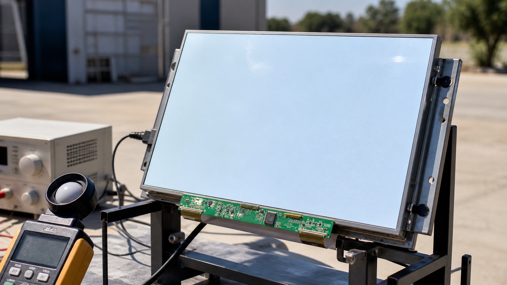
3. Power and Heat Must Be Designed Early
High-brightness backlights draw more current and convert a meaningful portion of that energy into heat. Heat affects LED lifetime, LCD liquid crystal behavior, touch controller stability, adhesive aging, and enclosure temperature. The backlight driver, cable, connector, and PCB copper must be sized for real current. If the product operates in sun load, thermal margin should be validated in a chamber or with a controlled solar simulation.
4. Dimming and Ambient Light Control
A display that is readable at noon may be painfully bright at night. Industrial systems should include PWM or analog dimming with enough resolution at low brightness. An ambient light sensor can improve usability and reduce LED stress, but the control loop must avoid visible pumping when a hand or shadow crosses the sensor. For safety-related interfaces, define a minimum readable brightness rather than allowing the display to dim too aggressively.
5. Backlight Lifetime and Derating
Datasheets often state LED lifetime as hours to 50 percent brightness at a specified temperature. That does not mean the display will look acceptable for the whole product life in every installation. Running the LED string below maximum current, improving heat spreading, and dimming when full output is not required all protect lifetime. For equipment with service contracts, calculate expected luminance after years of use rather than only initial brightness.
6. Validation Plan
A credible validation plan should use the final display stack, not an open-frame sample sitting on a desk. Build at least one sample with the intended cover lens, touch sensor, bonding method, cable, connector, backlight driver, enclosure, gasket, and firmware. Then test the conditions that match the product: operating temperature, storage temperature, vibration if relevant, ESD, EMI, repeated power cycling, brightness changes, sleep and resume, and long-duration operation.
For optical decisions, inspect the display under the lighting that customers will actually see. For electrical decisions, test with production cable length and realistic grounding. For mechanical decisions, measure tolerance stack-up and assembly repeatability. For software decisions, confirm boot behavior, error recovery, orientation, dimming, and touch calibration. A display that passes a one-hour bench test can still fail when installed in a sealed enclosure, driven at full brightness, or used by an operator wearing gloves.
7. Procurement and Lifecycle Review
Engineering teams should ask suppliers for more than a quotation. Useful documentation includes the LCD datasheet, module drawing, interface timing, backlight electrical data, optical test method, reliability report, RoHS and REACH status if required, packaging specification, PCN policy, and expected lifecycle. If the product is planned for long-term production, identify whether the panel, driver IC, touch controller, LED, polarizer, and adhesive are stable parts or subject to frequent substitution.
Second sources should be considered early. Even when a perfect drop-in alternate does not exist, knowing the nearest replacement helps the team preserve mechanical space, interface flexibility, and firmware options. A display can become a single point of failure for the whole product if the team treats it as a commodity part.
8. Engineering Checklist
- Measure readability with the final cover lens and touch stack.
- Confirm backlight current, driver efficiency, and connector rating.
- Validate enclosure temperature at maximum ambient and full backlight.
- Specify dimming range, PWM frequency, and minimum night brightness.
9. Final Recommendation
For embedded and industrial products, the best display choice is the one that remains readable, electrically stable, manufacturable, and available throughout the product lifecycle. Do not approve a display from a single specification or a clean-room demo photo. Approve it after the optical stack, interface, touch behavior, thermal path, firmware, and supplier controls have been reviewed together.
That approach takes more effort during design, but it reduces late redesigns, field complaints, and supply surprises. It is also the difference between a display that simply turns on and a display subsystem that supports the product reliably for years.
Related Engineering Context
For field mistakes that often appear after outdoor testing, read common mistakes when choosing a sunlight-readable TFT display. For a size-specific outdoor example, the article on 7 inch industrial TFT displays for outdoor use shows how brightness, bonding, and touch decisions come together.