eDP Display Panel Guide for High-Resolution Embedded Systems
A guide to embedded DisplayPort panel selection and integration, covering resolution scaling, AUX channel, link training, cable design, power sequencing, and industrial use cases.
Selecting a display for industrial PCs, diagnostic equipment, AI vision terminals, medical workstations, and premium HMI panels is rarely a one-variable decision. This guide focuses on using eDP panels for high-resolution embedded and industrial computer systems from an engineering point of view: optical behavior, electrical integration, mechanical stack-up, validation, supply risk, and field reliability.
eDP offers modern bandwidth and panel features, but link training, AUX communication, cable quality, and platform firmware support must be handled correctly. A common problem is assuming that an eDP connector means plug-and-play. In practice, incorrect lane configuration, weak cable design, or firmware that does not read the panel correctly can prevent stable startup.
The practical recommendation is simple: Use eDP when resolution, refresh rate, and modern platform support are more important than very long cable reach. The detailed work is in proving that decision against the real product environment, not against a marketing image or an isolated datasheet value.
1. Decision Summary
| Design area | Engineering implication | Practical note |
|---|---|---|
| Resolution scaling | Strong | Good for FHD, WUXGA, 2K and beyond |
| Cable length | Moderate | Shorter than external DisplayPort |
| EMI | Good with proper design | High speed still needs control |
| Firmware | Important | Link training must work reliably |
| Panel features | Modern | Supports advanced power and backlight options |
The table should not be used as a replacement for qualification testing. It is a way to focus the first design review. In a real project, the display decision should involve electrical engineering, mechanical engineering, firmware, industrial design, purchasing, quality, and the supplier application team. Each group sees a different failure mode: signal margin, enclosure tolerance, boot timing, touch feel, lifecycle risk, or cosmetic yield.
2. Why eDP Is Common in Modern Panels
Embedded DisplayPort replaced LVDS in many laptops and high-resolution embedded systems because it carries high bandwidth over fewer lanes and supports a packet-based architecture. For industrial designers, the main appeal is access to modern IPS panels with higher resolution, thinner cables, and better platform support on recent processors. It is a strong fit when the display sits inside the same enclosure as the main board.
3. Link Training and AUX Channel
Unlike simpler timing interfaces, eDP relies on communication between the source and sink. The AUX channel is used for configuration and link training. If firmware, operating system, or hardware does not handle this correctly, the panel may remain blank or fall back to an unstable mode. Validate cold boot, warm reboot, and resume behavior across the expected temperature range.
4. Cable, Connector, and Layout
eDP lanes operate at high speed, so impedance control, pair matching, connector quality, and shielding matter. Keep the cable route short and mechanically stable. Avoid sharp bends and noisy routing areas. If the display is in a hinged or serviceable assembly, define bend cycles and strain relief. Cable changes late in the project can create failures that look like firmware problems.
5. Backlight and Power Architecture
An eDP panel still needs panel power and backlight power. The backlight may be controlled through PWM, eDP AUX, or a separate driver depending on the module. Power sequencing requirements vary. Engineers should review panel logic voltage, inrush current, enable timing, brightness control, and fault handling before freezing the board design.
6. Validation Plan
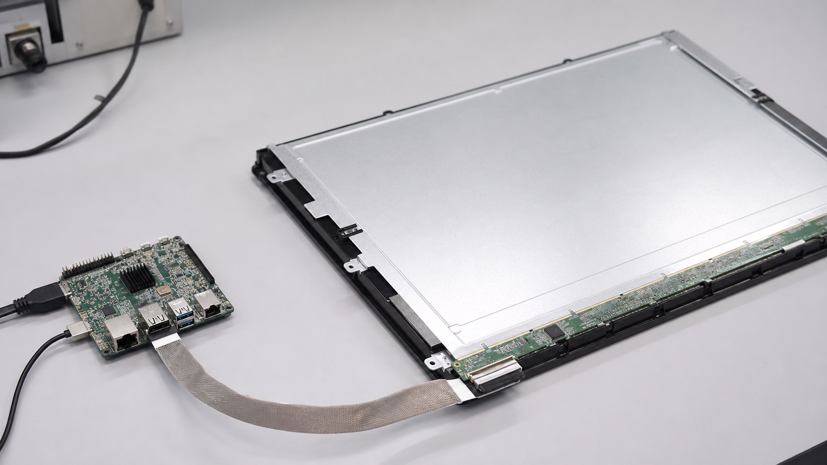
A credible validation plan should use the final display stack, not an open-frame sample sitting on a desk. Build at least one sample with the intended cover lens, touch sensor, bonding method, cable, connector, backlight driver, enclosure, gasket, and firmware. Then test the conditions that match the product: operating temperature, storage temperature, vibration if relevant, ESD, EMI, repeated power cycling, brightness changes, sleep and resume, and long-duration operation.
For optical decisions, inspect the display under the lighting that customers will actually see. For electrical decisions, test with production cable length and realistic grounding. For mechanical decisions, measure tolerance stack-up and assembly repeatability. For software decisions, confirm boot behavior, error recovery, orientation, dimming, and touch calibration. A display that passes a one-hour bench test can still fail when installed in a sealed enclosure, driven at full brightness, or used by an operator wearing gloves.
7. Procurement and Lifecycle Review
Engineering teams should ask suppliers for more than a quotation. Useful documentation includes the LCD datasheet, module drawing, interface timing, backlight electrical data, optical test method, reliability report, RoHS and REACH status if required, packaging specification, PCN policy, and expected lifecycle. If the product is planned for long-term production, identify whether the panel, driver IC, touch controller, LED, polarizer, and adhesive are stable parts or subject to frequent substitution.
Second sources should be considered early. Even when a perfect drop-in alternate does not exist, knowing the nearest replacement helps the team preserve mechanical space, interface flexibility, and firmware options. A display can become a single point of failure for the whole product if the team treats it as a commodity part.
8. Engineering Checklist
- Confirm lane count, link rate, and panel resolution with the host platform.
- Validate link training in firmware and operating system environments.
- Test production cable routing, shielding, and bend conditions.
- Document backlight control method and power sequencing.
9. Final Recommendation
For embedded and industrial products, the best display choice is the one that remains readable, electrically stable, manufacturable, and available throughout the product lifecycle. Do not approve a display from a single specification or a clean-room demo photo. Approve it after the optical stack, interface, touch behavior, thermal path, firmware, and supplier controls have been reviewed together.
That approach takes more effort during design, but it reduces late redesigns, field complaints, and supply surprises. It is also the difference between a display that simply turns on and a display subsystem that supports the product reliably for years.
Related Engineering Context
Before the enclosure is locked, compare this interface choice with the practical points in display interface decisions before enclosure design. If the display will run in harsh environments, the wide-temperature display design guide is a useful companion for reliability planning.