SPI vs RGB vs MIPI DSI: Which Interface Fits a Small TFT?
Compare SPI, parallel RGB, and MIPI DSI for small TFT displays using frame rate, pin count, memory, software, EMI, power, cable length, and product risk.
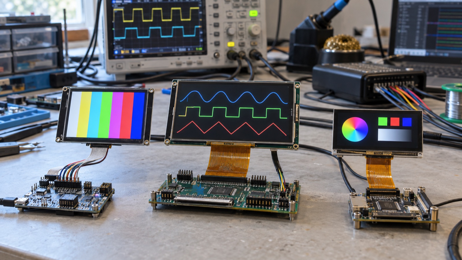
SPI, parallel RGB, and MIPI DSI can all connect a processor to a small TFT display. They do not solve the same problem.
SPI minimizes pins and works well with display controllers that hold their own frame memory. Parallel RGB sends a continuous pixel stream over many wires and is straightforward when the processor has a native LCD timing controller. MIPI DSI carries pixels and commands over a small number of high-speed differential lanes, but it demands compatible hardware, careful routing, and more involved software.
Choosing by connector size or headline bandwidth misses the architectural difference. The correct interface depends on what is inside the display, how often pixels change, where the frame buffer lives, and how much integration risk the project can accept.
First ask whether the display has a controller
Small SPI modules usually include a display-controller IC with internal GRAM (graphics RAM). The host writes commands and pixel data into that memory. The controller refreshes the LCD continuously afterward.
Many RGB panels are “dumb” from the host’s point of view. They accept pixel data, pixel clock, data-enable or sync signals, and must be refreshed continuously. The frame buffer normally sits in the MCU, MPU, FPGA, or external memory.
MIPI DSI can operate in different ways. Video mode behaves like a serialized continuous stream. Command mode allows command and image transactions, often with a panel-side frame buffer or update mechanism. The exact panel, host, and driver must agree.
This distinction changes memory use, idle power, update strategy, boot sequence, and software complexity before wire count is considered.
SPI: low pin count with a practical throughput ceiling
An SPI display connection may use clock, data, chip select, data/command, reset, and sometimes a read-data or tearing-effect signal. That is attractive for MCUs with limited pins and simple PCB layouts.
Advantages include:
- Few host pins.
- Easy connection through common MCU peripherals.
- The display controller refreshes the panel from local memory.
- Partial updates can reduce traffic for mostly static screens.
- Simple probing and bring-up at low speed.
Limitations include:
- Serial bandwidth limits full-screen frame rate.
- Command overhead and bus gaps reduce theoretical throughput.
- Reads may be slow or unavailable.
- Sharing the bus can complicate latency.
- Large animations expose tearing unless updates are synchronized.
For a 320×240 RGB565 screen at 30 full frames per second, active pixel payload alone is:
320 × 240 × 16 bits × 30 fps = 36.9 Mbit/s
An 80 MHz single-data-rate SPI clock appears sufficient on paper. In practice, command bytes, chip-select gaps, DMA setup, memory copies, other bus users, and imperfect utilization reduce margin. A static menu may feel excellent because only changed regions are sent; full-screen video may not.
Parallel RGB: predictable streaming at the cost of pins
An RGB interface commonly carries 16, 18, or 24 data lines plus pixel clock and control signals. The host sends every pixel in raster order for every frame.
Advantages include:
- Simple relationship between framebuffer and panel timing.
- Predictable full-frame refresh.
- Broad support in embedded LCD controllers.
- No packet protocol between host and panel.
- Easy matching to many 4.3-, 5-, and 7-inch modules.
Trade-offs include:
- High pin count and wider connectors.
- Many switching lines can increase EMI.
- Continuous data consumes memory and I/O bandwidth.
- Cable length and skew become harder to control.
- The host must generate exact timing without interruption.
RGB is often the least surprising option for an MCU with a dedicated LTDC/LCDC peripheral and enough external memory. It is a poor fit if the processor lacks that peripheral or if the enclosure forces a long, narrow interconnect.
MIPI DSI: high bandwidth and low pin count, with tighter integration
MIPI DSI uses a clock lane in many D-PHY implementations plus one or more differential data lanes. High-speed data and low-power signaling share the physical connection. The protocol can carry pixel streams, commands, and status transactions.
MIPI Alliance describes DSI as a high-speed interface intended to combine performance, low power, low EMI, and reduced pin count. Those benefits are real when the processor and display already support compatible DSI modes.
The work appears elsewhere:
- Lane rate and lane count must fit the timing.
- D-PHY routing needs controlled impedance and close pair matching.
- Initialization command sequences may be panel-specific.
- Video/command mode behavior must match the host.
- Clock mode, low-power transitions, and escape sequences can affect bring-up.
- Debugging often needs better tools than a basic oscilloscope probe.
The MIPI DSI hardware and software integration checks should be reviewed before treating DSI as a connector-only choice.
Quick comparison
| Factor | SPI | Parallel RGB | MIPI DSI |
|---|---|---|---|
| Typical pins | Low | High | Low |
| Panel-side memory | Common | Usually no | Depends on mode/panel |
| Full-screen bandwidth | Limited | Moderate to high | High and scalable |
| Partial updates | Natural | Host renders continuously | Strong in command mode |
| Host hardware | Common SPI + DMA | LCD timing controller | DSI host + D-PHY |
| PCB routing | Simple at modest speed | Many single-ended lines | Few but high-speed differential lanes |
| Software | Controller commands | Timing + framebuffer | Timing, packets, PHY, initialization |
| EMI risk | Edge-rate dependent | Many simultaneous signals | Controlled differential link |
| Best fit | Static/small MCU UI | Native MCU/MPU LCD output | Compact high-resolution design |
The table indicates tendencies. A fast quad-SPI controller, low-resolution RGB panel, or mature DSI platform can shift the balance.
Frame rate is not the only performance metric
A UI does not need video frame rate everywhere. Consider three workloads:
- Mostly static instrument: values change a few times per second. SPI partial updates may use little bandwidth.
- Animated control interface: menus and charts update continuously. RGB or DSI can produce more consistent motion.
- Camera preview: most pixels change every frame. Link throughput and end-to-end latency dominate.
SPI can also produce a responsive UI when touch feedback updates a small region immediately and background areas update later. Conversely, an RGB interface can still feel slow if the rendering engine misses frame deadlines.
Define worst-case changed area, required frame rate, and latency rather than writing “smooth UI” in the specification.
Memory architecture often decides the interface
RGB and DSI video mode commonly require one or more full frame buffers at the host. A 800×480 RGB565 frame uses about 768 kB; RGB888 uses about 1.15 MB. Double buffering and graphics assets add more.
An MCU with only internal SRAM may favor a controller-based SPI module. Adding SDRAM solely for a continuous RGB framebuffer increases BOM, routing, power, and firmware work.
An MPU with DDR and a mature display subsystem may handle RGB or DSI naturally. In that case, adding an SPI controller can introduce unnecessary copying and color-format conversion.
The 5-inch 800×480 IPS module format is a useful scale for comparing these architectures: the resolution is manageable for many MPUs, but full-screen serial updates can expose the limits of a small MCU.
Cable length and mechanical placement matter
SPI at modest clock rates can tolerate simple short wiring, but faster edges still need a return path and controlled layout. Parallel RGB becomes increasingly sensitive to skew, ringing, and emissions as pixel clock and cable length rise. MIPI D-PHY is designed for high-speed differential transmission, yet it normally expects short, well-controlled channels.
Do not assume “differential” means “any cable length.” Check the PHY, connector, FPC construction, insertion loss, pair skew, and reference plane. If the processor and display are far apart, LVDS or eDP may be more appropriate than any of these small-panel options.
Review the display cable path before enclosure tooling so the electrical choice does not create an impossible bend or unserviceable connector.
EMI is shaped by implementation
Parallel RGB switches many single-ended traces simultaneously. Series termination close to the source, continuous return planes, short routing, and controlled edge rates can make it manageable.
SPI uses fewer lines but can still radiate if a fast clock crosses gaps, runs through a long unshielded cable, or rings badly. Reducing the configured clock is not a substitute for good return-path design.
MIPI DSI reduces common-mode radiation when differential pairs are routed correctly. Pair imbalance, connector discontinuity, mode transitions, and poor ground continuity can erase that advantage.
EMI should be measured with the production cable, display, enclosure, and active image patterns. A static screen may not create the same traffic as animation or video.
Power behavior differs by architecture
SPI modules with controller memory can stop host traffic while a static image remains visible, although the controller, LCD, and backlight still consume power. RGB video usually requires continuous pixel clock and memory access. DSI command mode can reduce traffic for static content, while video mode remains continuous.
Panel sleep, deep standby, ULPS, backlight control, and wake latency are implementation-specific. Verify whether the display loses GRAM contents in sleep and whether firmware must redraw the frame after wake.
A selection process that catches risk early
Step 1: Confirm host interfaces
List real peripheral instances, supported pixel formats, maximum clocks, DMA paths, lane rates, and pin conflicts. Marketing statements such as “supports display” are not enough.
Step 2: Confirm panel architecture
Identify controller IC, internal memory, native interface mode, required commands, timing, and reset behavior.
Step 3: Calculate worst-case traffic
Use native resolution, color depth, refresh rate, blanking, packet overhead, and realistic bus efficiency. The display link bandwidth and lane-count method provides worked calculations.
Step 4: Check memory and render time
Measure a worst-case screen, not a color-fill demo. Include asset decoding, alpha blending, rotation, and touch feedback.
Step 5: Prototype the final interconnect
Use intended cable length, connector, layer stack, termination, and enclosure. Log errors and inspect emissions.
Step 6: Test boot, sleep, and recovery
Verify reset, first frame, backlight timing, brownout, repeated power cycles, and resume from every supported low-power state.
Practical recommendations
- Choose SPI for small, mostly static interfaces when low pin count and MCU simplicity matter more than full-screen frame rate.
- Choose parallel RGB when the host has a proven LCD controller, sufficient memory, and a short internal connection.
- Choose MIPI DSI when pin count and higher resolution justify the integration effort and both ends have compatible, documented support.
Do not insert a bridge just to preserve an early assumption. Sometimes selecting a panel that matches the processor is cheaper and more reliable than translating protocols.
FAQ
Can SPI drive an 800×480 display?
Yes, but acceptable performance depends on SPI width/rate, controller behavior, changed area, color depth, and required frame rate. Full-screen animation is much harder than partial updates.
Is MIPI DSI always faster than parallel RGB?
DSI offers high aggregate bandwidth with fewer pins, but actual capacity depends on lane count, lane rate, packet overhead, and mode. RGB performance depends mainly on pixel clock and bus width.
Does an RGB panel need external RAM?
The panel usually does not store a full frame, so the host needs a framebuffer somewhere. Whether external RAM is required depends on resolution, color format, buffering, and available internal memory.
Can a small TFT use both SPI and RGB?
Some controller-based modules expose multiple modes, but the pin strapping, controller configuration, and available features may differ. Confirm the exact module schematic and controller datasheet.
Technical references
- MIPI Alliance DSI overview — describes DSI’s high-speed, low-power, low-EMI, reduced-pin-count goals and supported modes.
- Microchip display hardware example — documents a small TFT module supporting serial, parallel, and RGB interface modes.