PCAP Through Thick Cover Glass: Design Limits and Tuning Methods
Understand projected-capacitive touch through thick glass, including dielectric stack, electrode design, controller tuning, noise margin, gloves, water, and validation.
“Can this touchscreen work through 6 mm of glass?” is a useful starting question, but it cannot be answered from glass thickness alone. The controller senses a small change in an electric field shaped by the electrodes, cover material, adhesive, finger, grounding, and nearby display electronics.
Increasing sensitivity may recover a touch on the bench. The harder task is retaining enough margin to reject noise and water while detecting the intended finger or glove at the edge of a production assembly.
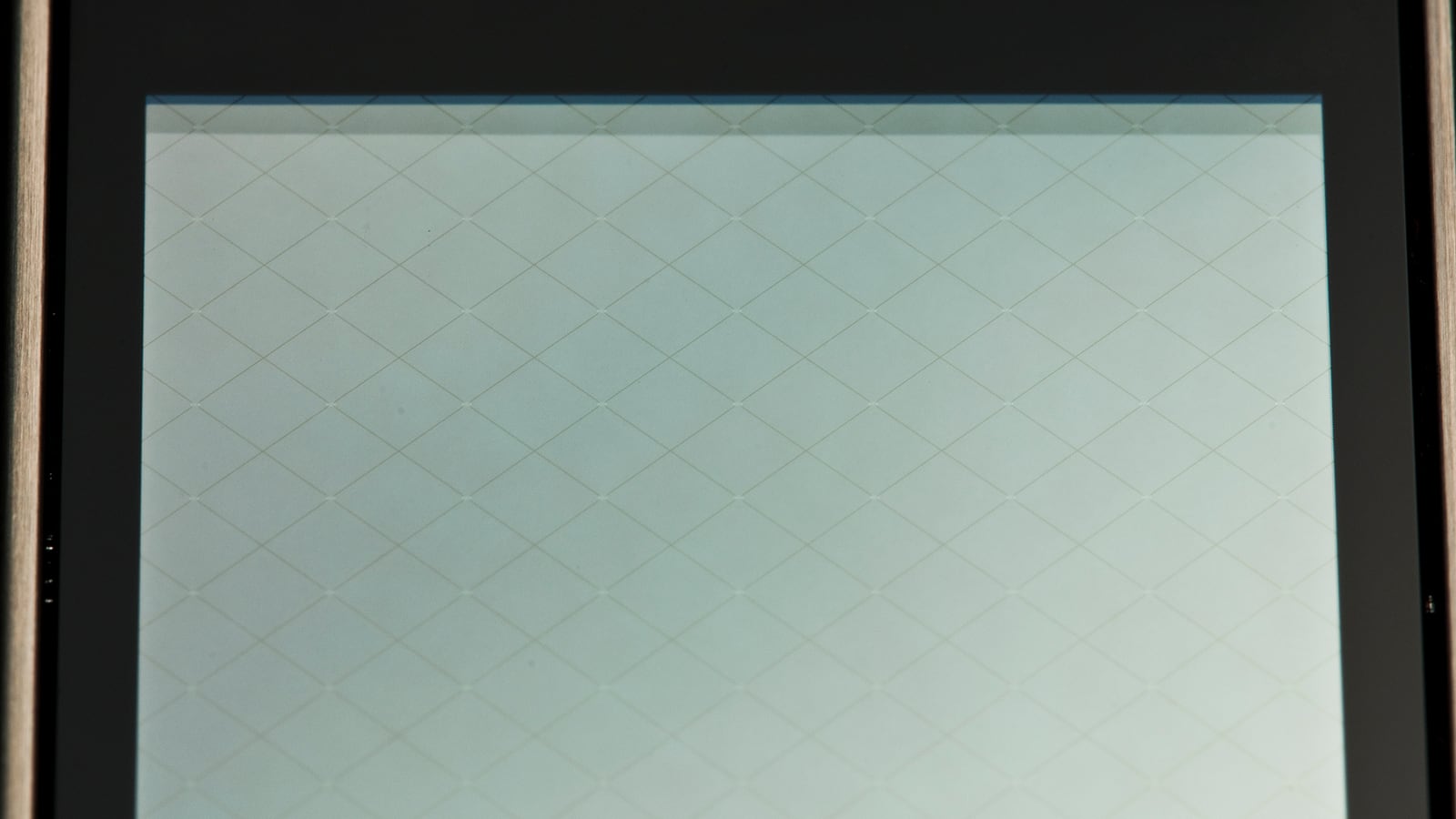
Photograph: Medvedev, CC BY 3.0, via Wikimedia Commons. Resized and cropped. It shows a real capacitive electrode pattern, not a thick-glass demonstration or a tested thickness rating.

What changes when the cover gets thicker
A thicker cover increases the physical separation between the finger and the sensor. The touch-related signal generally becomes smaller, though the exact relationship depends on the sensing architecture and geometry. That reduces the separation between a valid touch and background variation.
The remaining margin has to accommodate:
- Smaller fingers and off-centre touches.
- Gloves and weak body coupling.
- Temperature and humidity changes.
- Display, backlight, charger, and radio interference.
- Adhesive and glass tolerances.
- Water films or droplets.
- Production variation in sensor and controller.
The question is therefore not whether one sample registers a finger. It is whether the worst valid touch remains distinguishable from the worst expected noise and unintended interaction.
Describe the full dielectric stack
List every layer between the finger and electrodes: coating, cover glass, optical adhesive, protective film, and any air gap. Include thickness tolerances and material properties supplied for the intended operating conditions.
For an idealized parallel-plate stack, capacitance per area is proportional to:
C/A ≈ ε0 / Σ(ti / εri)
Here ti is layer thickness and εri its relative permittivity. This is a useful way to see why a low-permittivity air gap can matter disproportionately. Real PCAP sensing uses fringing fields and an interacting electrode network, so the equation is not a predictor of maximum touch thickness or a substitute for controller simulation and measurement.
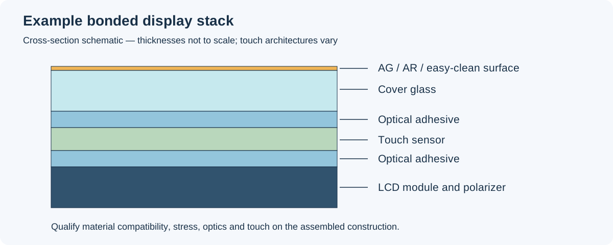
Example construction; dimensions are not to scale. The cover-to-electrode distance is the relevant stack, not the total display-module thickness.
This distinction matters when someone adds a protective window above an already bonded touch module. The extra glass and air space can change the sensing conditions substantially, even though the original module remains electrically unchanged.
A controller rating is conditional
Some controller families explicitly support thick lenses, but their published capability belongs to defined sensor sizes, configurations, materials, and conditions. It is not a universal rating for every electrode pattern and glove combination.
For example, Microchip lists thick-lens capability among the features of its ATMXT144U controller, while other maXTouch products address different panel sizes and stack requirements. Use such data to shortlist parts, then request the supplier’s conditions and tuning guidance for the actual sensor.
Do not assume the maximum lens thickness and maximum glove thickness can be used simultaneously. Ask whether the required combination, contact count, edge accuracy, and wet behavior have been validated together.
Sensor geometry can matter as much as the IC
Electrode pitch, shape, routing, border design, and parasitic capacitance influence field coupling and noise. A controller cannot fully compensate for a sensor whose signal distribution becomes too weak or uneven through the chosen cover.
Thick-cover designs may require a different sensor pattern. That can affect spatial resolution, routing, edge performance, and display-noise coupling. Review the smallest required target and touch position before accepting a geometry optimized only for centre-screen detection.
For a custom assembly, freeze the cover stack, electrode revision, controller, tuning file, and test matrix together in the custom TFT touch-stack design requirements. A later adhesive substitution can become a touch-system change, even when the glass drawing stays the same.
Tune from raw signal evidence
Start with the controller vendor’s recommended configuration and diagnostic tools. Collect baseline, touch delta, and noise information using the vendor’s definitions. Different tools may report different signal-to-noise metrics, so retain raw captures and document the calculation rather than comparing unnamed ratios.
Map signal and noise at the centre, edges, and corners. Repeat with the weakest intended touch and the noisiest valid operating state. Observe drift over time and temperature before changing thresholds.
Useful tuning controls may include drive level, acquisition time, averaging, scan frequency, filtering, threshold, and contact validation. Availability and side effects are controller-specific. Increasing drive can improve signal but also changes power or emissions; heavier filtering can reduce noise at the cost of response time.
Change one parameter group at a time and keep versioned configuration files. A tuning session without saved settings and measurement conditions is difficult to reproduce.
Threshold is only one part of the decision
Lowering a threshold can increase detection probability, but it also admits more noise. A stable touch decision may depend on spatial shape, multiple frames, contact size, hysteresis, and baseline behavior.
Check approach, touch, drag, and release separately. A controller can register a press yet lose the finger during a slow drag, or retain a contact after lift-off. Those failures are easy to miss when validation consists of tapping large buttons.
Include latency after any filtering change. A thick-glass mode that feels sluggish may be technically detecting every touch while failing the intended interaction.
Separate gloves, water, and thick glass
These conditions interact, but they are not interchangeable test labels. A glove changes finger coupling and contact area. A water droplet can create an unintended conductive object. A water film can connect regions that are otherwise separate.
Build a matrix around real combinations:
| Condition | Key question |
|---|---|
| Dry bare finger | Minimum signal and edge accuracy |
| Specified dry glove | Reliable first touch, drag, and release |
| Damp glove | Contact stability and false events |
| Isolated droplets | Rejection without losing intended touches |
| Water film or cleaning residue | Safe behavior and recovery after drying |
| Floating user/product | Margin with weak grounding |
Use the actual glove material and thickness. “Glove mode” is not a single standard test. The industrial PCAP glove and water validation method provides the broader qualification context.
Test electrical noise in the installed product
Run the backlight through its dimming range, exercise radios, connect approved power adapters, and switch relevant loads. A clean bench supply can conceal charger noise; an open-frame sample can have different coupling from the grounded enclosure.
Inspect the power and ground arrangement before trying increasingly aggressive filtering. Keep display and touch cables in their released routes. If a noise problem tracks PWM duty or a radio transmission, record that operating condition explicitly.
The touch-controller interface choice also affects recovery and diagnostics, but changing the host bus does not automatically fix a weak sensor-to-finger signal.
Design validation around tolerances
Use minimum and maximum cover and adhesive thicknesses, multiple glass and sensor lots, and representative controller samples. Include black-border registration, bezel proximity, and assembly preload. Mechanical stress can change the stack and create optical artifacts as well as touch variation.
Measure edge and corner performance in the final enclosure. Run small-target selection, slow diagonal drags, multi-touch, lift-off, power cycling, and suspend/resume. Repeat important checks at operating-temperature limits and after the environmental exposures required by the product.
Keep acceptance measurable: missed-touch rate under a defined procedure, false-event count during a defined no-touch exposure, position error, drag continuity, release delay, and recovery behavior. Choose limits from the actual user task rather than copying a controller brochure.
What to request from the supplier
Ask for the validated cover construction, electrode revision, controller firmware, tuning-file checksum, diagnostic captures, test conditions, and change-notification policy. Clarify whether thick-cover and glove performance were demonstrated on the same assembly.
Coordinate this with cover-glass thickness and mechanical selection. Increasing thickness to meet an impact target may require a new sensor or controller configuration; reducing thickness to improve touch may require better enclosure support.
A successful thick-glass design preserves margin across those trade-offs. Freeze the complete stack only after it has passed with the intended users, gloves, electrical states, and production tolerances. The thickness value is then one documented property of a qualified assembly, rather than a promise that firmware alone has to fulfil.