OCA vs OCR Optical Bonding Materials for Industrial Displays
Compare OCA film and OCR liquid optical bonding materials by gap filling, lamination, cure, LCD stress, rework, yield, and industrial reliability requirements.
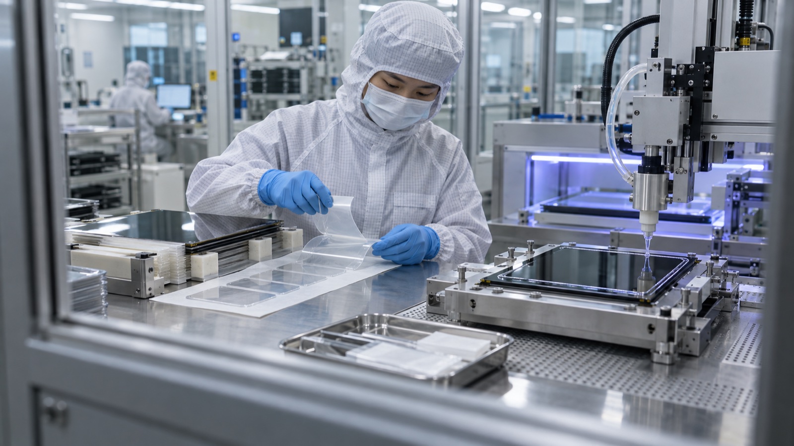
The first optical-bonding quote often reduces the decision to two labels: OCA film or OCR liquid resin. Both can replace an air gap with a transparent adhesive, but they reach that result through different processes. Those processes affect thickness control, ink-step coverage, bubbles, LCD stress, equipment, rework, and production yield.
The better choice follows the complete display stack and factory process. A material with excellent optical data can still be a poor choice if it cannot be laminated, cured, inspected, and repaired consistently in the intended assembly.
Clarify the terminology with the supplier
OCA usually means optically clear adhesive supplied as a film, roll, or die-cut sheet. It is often a pressure-sensitive acrylic, although chemistry and curing requirements vary.
OCR means optically clear resin, usually dispensed as a liquid and cured after assembly. LOCA, or liquid optically clear adhesive, is another common term for liquid optical-bonding materials.
These are commercial categories rather than a complete material specification. Some film OCAs require UV curing; some liquid systems use different cure mechanisms. Ask for the actual product, chemistry, thickness, cure conditions, and approved substrates.
3M’s optical-adhesive technical resources describe film and liquid forms and note that lamination, overflow control, and cure steps differ. Henkel identifies liquid OCR and tape OCA as the two common categories in its optical-bonding material overview.
What both approaches can improve
Removing an air gap reduces internal reflections when the adhesive’s refractive index is suitable for the adjacent layers. It can also prevent condensation in that gap and mechanically couple the front stack.
The result depends on the whole construction. Adhesive transmission, haze, color, thickness, surface treatment, and cover reflections still matter. Optical bonding does not remove the outer air-to-glass reflection, and a bonded display still needs thermal and mechanical qualification.
Review the optical bonding and air-gap trade-offs before selecting the adhesive process.
Where OCA film fits well
Film begins with a defined nominal thickness. Die cutting can control the outline, holes, and border clearance. For flat, well-controlled stacks, automated lamination can offer repeatable material placement and clean handling.
Typical process steps include surface cleaning, liner removal, alignment, roller or vacuum lamination, bubble removal under controlled conditions, and any required cure. The exact process comes from the adhesive supplier and equipment capability.
Risks include trapped particles, folds, bubbles, poor wet-out, excessive lamination pressure, and inability to conform over a tall printed border. The film thickness does not guarantee uniform assembled thickness if substrate bow or compressibility is significant.
Where liquid OCR fits well
Liquid resin can flow into a defined gap and accommodate some topography. It can suit stacks where cover shape, large area, or border geometry makes film lamination difficult.
The process must control dispense volume and pattern, resin temperature and viscosity, degassing, placement speed, gap, edge containment, and cure. Underfill leaves voids; overfill creates overflow and contamination. Resin can migrate into unintended areas unless a dam or seal controls it.
Curing adds its own variables: wavelength, irradiance, dose, exposure uniformity, oxygen effects for some chemistries, and shadowed regions under black ink. “UV cured” needs a defined process and evidence that the whole bond reaches the required state.
Compare the process, not just the material label
| Decision area | OCA film | Liquid OCR / LOCA |
|---|---|---|
| Material placement | Die-cut or roll film alignment | Metered dispense and controlled flow |
| Thickness | Supplied film thickness plus assembly effects | Gap control plus dispense/cure behavior |
| Printed border | Conformability depends on film and step geometry | Flow can fill steps; shadow cure must be checked |
| Main bubble risks | Trapped air, poor wet-out, particles | Entrained gas, flow fronts, outgassing |
| Equipment | Lamination and bubble-removal tools | Dispense, alignment, gap, containment, cure tools |
| LCD stress | Lamination pressure and adhesive mechanics | Placement pressure, cure shrinkage, adhesive mechanics |
| Rework | Product- and process-dependent | Product- and process-dependent |
Neither column guarantees better yield. Compare pilot builds using the intended machinery, operators, environment, and part tolerances.
Ink steps need an explicit cross-section
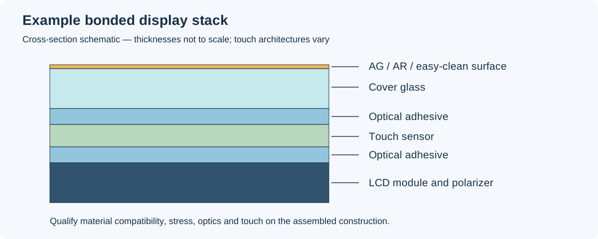
Each adhesive interface needs its own material and process definition; thicknesses are schematic.
A black printed border creates a height change. For film, ask how much step the selected adhesive can cover at the released thickness and lamination conditions. Do not assume an arbitrary percentage applies to every OCA.
For liquid resin, examine the flow path and cure access beneath the border. A filled gap that looks clear immediately may still contain undercured material in a shadow region.
The drawing should show glass, print, sensor, adhesive, panel polarizer, edge dam, and seal. Include tolerances and keep-out areas. Coordinate it with the industrial cover-glass and printed-border design.
LCD mura is a mechanical warning
LCDs are sensitive to pressure and stress. Uneven adhesive thickness, substrate bow, lamination force, cure shrinkage, or differential expansion can distort the cell and create visible nonuniformity.
Inspect uniform dark gray, mid-gray, and white patterns before bonding, immediately after bonding, after stabilization, and after environmental exposure. Record whether defects relax or persist.
3M specifically notes the need for a softer lamination approach to manage LCD mura in its technical guidance. A process accepted for another display technology should not be transferred to an LCD without validation.
Material compatibility reaches beyond glass
The adhesive may contact polarizers, coatings, inks, ITO, metal mesh, flexible sensor films, plastics, and edge seals. Review:
- Adhesion and chemical compatibility.
- Ionic contamination and corrosion risk.
- Moisture uptake and permeability.
- Outgassing from plastic substrates.
- UV stability and yellowing.
- Dielectric properties affecting touch.
- Modulus and stress over temperature.
- Cure shrinkage and residual chemistry.
For plastic lenses, outgassing can form bubbles after a visually clean lamination. Supplier data should use comparable substrates, but only the target stack establishes product performance.
Read optical data with the test construction
Transmission and haze values depend on specimen thickness, substrate, wavelength range, and reference correction. An adhesive-only result cannot be compared blindly with a glass/adhesive/glass result.
Ask for the method, sample construction, and aged values. Check color shift, not only initial transmission. Use a display haze and clarity comparison to distinguish light loss from scattering and fine-detail blur.
Rework needs a demonstrated procedure
“Reworkable” can mean separating the cover without breaking it, recovering the expensive LCD, or simply removing uncured overflow. Those are different outcomes.
Request a practical demonstration on the target stack. Record separation force or temperature, cleaning chemistry, residue, polarizer damage, touch function, recovery yield, and time. Include the cost of discarded cover glass and labor when comparing total cost.
If rework is not feasible, the process needs stronger prevention and inspection before the irreversible step.
A pilot qualification that answers production questions
Build across realistic tolerance corners: minimum and maximum print height, cover bow, adhesive thickness or gap, and permitted process settings. Include multiple material lots where possible.
Track:
- First-pass cosmetic and functional yield.
- Bubble, particle, edge, and alignment defects by location.
- Mura before and after bonding.
- Touch performance and electrical noise margin.
- Optical measurements after stabilization.
- Thermal cycling, humidity, UV, and temperature exposure appropriate to the application.
- Delamination, yellowing, bubbles, and edge changes after aging.
- Rework outcome and recovered-unit performance.
A high-resolution 10.1-inch industrial IPS display can expose subtle stress and contamination, but the pilot must use the final enclosure support and optical stack before release.
What to request in the quote
Ask for the material part number, process flow, tolerances, cosmetic criteria, traceability, cure verification where applicable, reliability conditions, expected yield, rework policy, and change-notification agreement. The optical-bonding qualification workflow should be attached to the assembly specification.
Choose OCA or OCR after comparing those records. The successful material is the one that gives the required optics and reliability through a repeatable production process, with a clear plan for defects and service.