LCD Power Sequencing: Rails, Reset, Backlight, and Safe Shutdown
Design and test LCD power sequencing for panel rails, reset, video, bridge ICs, touch, and backlight without flashes, latch-up, or back-powering.
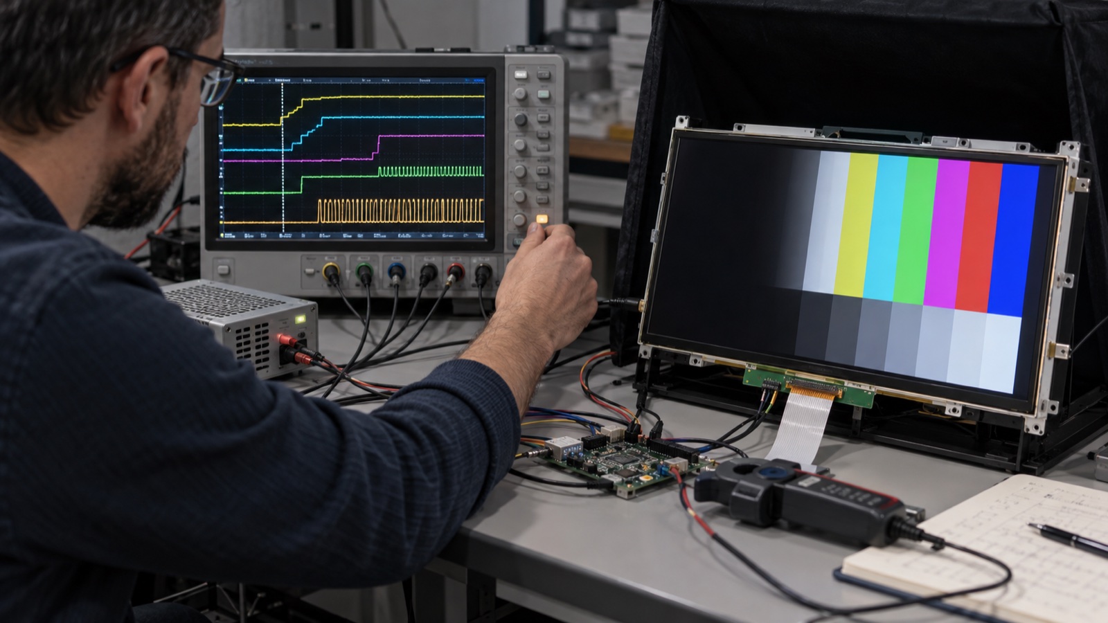
An LCD can show a correct image for hours and still have a bad power sequence. The evidence appears during transitions: a white flash at boot, random vertical lines, a panel that starts only after a second reset, extra current while “off,” or permanent damage after repeated power cycles.
Display power-up is not simply “apply 3.3 V and start video.” A module may contain logic power, analog bias generation, gate rails, a timing controller, reset and standby inputs, an interface receiver, nonvolatile configuration, touch electronics, and a separate LED backlight supply. The order and delay between those elements matter.
Use the exact panel and bridge datasheets as the authority. The sequence below is an engineering framework for reviewing those requirements, not a replacement for them.
Identify every powered domain
Draw the display power tree before writing firmware. Typical domains include:
- Panel logic rail, such as 1.8 V, 3.3 V, 5 V, or 12 V.
- LCD bias rails generated on-module or externally.
- Interface I/O rail.
- MIPI D-PHY, LVDS, or eDP receiver rail.
- Bridge-IC core, I/O, PLL, and analog rails.
- Touch-controller and touch-sensor supply.
- LED backlight power.
- Backlight enable and PWM reference domain.
- Reset, standby, and panel-enable pull-up rails.
Mark which signals can exist when each rail is off. A data line driven into an unpowered receiver can feed current through protection diodes, partially power internal circuits, and create an undefined state.
The datasheet timing diagram is a set of inequalities
Power-sequence diagrams usually define intervals such as:
- Supply rise time.
- Delay from valid power to reset release.
- Delay from reset release to commands.
- Delay from initialization to valid video.
- Number of black frames before backlight enable.
- Minimum backlight-off time before video stops.
- Supply discharge time.
- Minimum off-time before restart.
Do not convert a minimum delay into an exact sleep without considering tolerance. If the datasheet requires “at least 10 ms,” firmware scheduling, oscillator error, regulator settling, and temperature should not produce 10.0 ms nominal.
Record each limit in a table with owner and evidence:
| Event | Requirement | Implementation | Measured worst case |
|---|---|---|---|
| Panel VDD valid → reset release | Datasheet minimum | GPIO state machine | Scope result |
| Reset release → configuration | Datasheet minimum | Driver delay | Logic trace |
| Valid video → backlight enable | Frames or time | TCON event + timer | Optical/scope result |
| Backlight off → video stop | Datasheet minimum | Shutdown state | Scope result |
| Video stop → VDD off | Datasheet minimum | Load-switch control | Scope result |
A robust power-up order
A common sequence is:
- Hold backlight disabled.
- Hold panel and bridge reset/standby in the required state.
- Keep interface signals quiet or in their specified off state.
- Enable required power rails in order.
- Wait for regulators, clocks, and power-good signals to settle.
- Release reset according to timing limits.
- Program the bridge and panel controller.
- Start valid black video or complete link training.
- Wait the required frames/time.
- Enable the backlight and ramp brightness.
The exact order can differ. Some eDP panels assert HPD only after panel power; some DSI panels need low-power commands before video; some controller-based displays require reset pulses with specific widths.
The important user-facing rule is simple: do not illuminate the panel until its pixel state is controlled. A backlight enabled before valid black data is the usual cause of boot flashes and random patterns.
For example, a 7-inch high-brightness LVDS panel still requires its exact module timing to be followed; interface type and brightness do not define the safe startup sequence.
Safe shutdown is usually the reverse—but verify it
A common shutdown flow is:
- Fade or disable backlight.
- Maintain valid video for the specified interval.
- Send display-off or sleep commands where required.
- Stop the high-speed link or place it in the required idle state.
- Assert reset/standby.
- Remove panel and bridge rails in the specified order.
- Wait for discharge and minimum off-time before restart.
“Reverse the startup order” is a useful initial model, not a universal rule. Some devices require special discharge timing, link shutdown, or command sequences.
TI’s power-sequencing guidance notes that downstream devices should not be enabled before upstream rails are ready and describes feedback/power-good methods that verify a rail before proceeding. That is safer than relying on open-loop delays alone when startup varies with load or temperature.
Reset is not a substitute for power cycling
Reset may initialize digital logic without discharging analog or bias nodes. A panel that recovers from software reset under normal conditions can remain stuck after a brownout.
Test separately:
- Hardware reset pulse.
- Software display-off/on commands.
- Panel power cycle with host still running.
- Complete system power cycle.
- Short interruption that does not fully discharge rails.
- Repeated restart at minimum off-time.
If the datasheet specifies a minimum time below a voltage threshold, measure that threshold. A fixed “500 ms off” delay does not guarantee the rail reached zero when large capacitors, leakage, or back-power paths remain.
Back-powering creates the most confusing faults
Back-power occurs when a signal or secondary rail feeds an unpowered domain. Common paths include:
- RGB data driven while panel VDD is off.
- I²C pull-ups tied to an always-on host rail.
- PWM or enable high while the backlight driver is unpowered.
- HDMI, eDP AUX, HPD, or bridge GPIO connected across domains.
- Touch interrupt or reset lines with mismatched supplies.
- USB-powered touch electronics attached to an off display.
Symptoms include slow discharge, unexpected current, partial startup, latch-up risk, or GPIO voltage when the module is supposedly off.
Use level shifters with powered-off protection, series resistance where appropriate, load switches, correct pull-up domains, or firmware pin states. Verify current and pin voltage in every off state.
Brownout is harder than a clean shutdown
During a clean shutdown, firmware can disable the backlight and stop video first. During brownout, input power collapses while different regulators and capacitors decay at different rates.
Design for:
- Supervisor detection early enough to act.
- Backlight disable with hardware priority.
- Known reset behavior as rails fall.
- Controlled discharge where required.
- No interface drive from a longer-lived host rail.
- Restart only after a complete, valid off interval.
TI notes that uncontrolled power-off can violate rail ordering and describes supervisors as a way to detect falling input early. For a display system, that warning can be used to blank the backlight, stop writes, and put bridges into reset before logic becomes unpredictable.
Bridge ICs add another sequence
A bridge between DSI, RGB, LVDS, eDP, or HDMI has its own supplies, reference clock, reset, configuration, PLL lock, and output enable.
Questions include:
- Must input clock be present before reset release?
- Can output toggle before registers are programmed?
- When is PLL lock valid?
- Does the panel need stable output before backlight enable?
- What happens if the source restarts but the bridge remains powered?
- Can I²C access occur before all bridge rails are valid?
The display bridge IC selection checklist covers protocol direction and timing limits; its power states should be integrated into one system sequence, not handled as a separate driver afterthought.
Interface-specific details
Parallel RGB
Keep clock and data in the panel’s required state before VDD, during reset, and during shutdown. Confirm whether DE/sync may toggle while the panel is in standby.
LVDS
Avoid uncontrolled common-mode or data toggling into an unpowered receiver. Check transmitter shutdown state and mapping after reset. The LVDS panel signal and timing review should include power-off behavior.
MIPI DSI
Confirm LP-11/stop state, clock behavior, reset timing, sleep-out delay, initialization command order, and the transition into video mode. Use the MIPI DSI bring-up sequence for panel-specific command handling.
eDP
Coordinate panel power, HPD, AUX readiness, link training, valid black video, and LED converter control. A panel datasheet may specify separate timing windows for each.
Implement a state machine, not scattered delays
A state machine makes the sequence observable and recoverable:
OFF
  -> RAILS_START
  -> WAIT_POWER_GOOD
  -> RESET_RELEASE
  -> CONFIGURE
  -> LINK_START
  -> BLACK_FRAME_WAIT
  -> BACKLIGHT_RAMP
  -> RUN
Shutdown and fault paths should be explicit. Each state should have:
- Entry action.
- Required input or timer.
- Timeout.
- Logged failure reason.
- Safe fallback state.
If configuration fails, do not enable the backlight and hope the image appears. Return to a controlled reset/off state, observe minimum off-time, and retry a limited number of times.
Measure the sequence with the right tools
Use a multi-channel oscilloscope or mixed-signal instrument. Useful channels include:
- Panel VDD.
- Bridge rail or power-good.
- Reset.
- Pixel clock/DSI activity/LVDS clock.
- Backlight enable.
- Backlight current or LED output.
Trigger on the earliest enable and capture from before power rise through first illumination. Repeat for shutdown, restart, brownout, sleep, and wake.
Where channel count is limited, take multiple captures with one reference signal held constant. Save annotated captures in the release package. The display bring-up fault-isolation workflow is much faster when a known-good timing capture exists.
Test across corners and repeated cycles
Sequence timing changes with regulator soft start, capacitance, input voltage, load, and temperature. Test:
- Minimum and maximum supply voltage.
- Cold and hot operation.
- Fast and slow input ramps.
- Short and long off intervals.
- Rapid user button presses.
- Watchdog reset during startup.
- Host crash while backlight is on.
- Cable disconnect where service permits it.
- Hundreds or thousands of automated cycles.
Watch for intermittent flashes, elevated off current, missed initialization, image corruption, touch failure, and bridge error flags.
Release checklist
- Exact panel and bridge revisions are recorded.
- Every rail and signal domain is mapped.
- Datasheet timing limits are translated into requirements.
- Startup, shutdown, sleep, wake, reset, and brownout are defined.
- Back-power paths are blocked or accepted with evidence.
- Backlight remains off until valid image data is stable.
- Minimum off-time is enforced by measured voltage, time, or both.
- Scope captures pass at voltage and temperature corners.
- Automated cycling shows no intermittent state.
- Firmware logs the state and failure point.
FAQ
Why does an LCD flash white during boot?
The backlight is often enabled before valid black pixel data or panel initialization. Delay illumination until the link and image state are controlled.
Can firmware delays guarantee power sequencing?
They can implement timing, but power-good feedback and measurement provide better evidence when rail settling varies. Hardware should also handle brownout and unsafe off states.
Should the backlight power up with the LCD rail?
The supply may be available earlier, but LED enable should normally remain inactive until panel initialization and valid video meet the module timing requirement.
Why does the display work only after a second reset?
Possible causes include insufficient rail settling, reset release too early, incomplete discharge, missing clock, or bridge configuration before its power/PLL is ready.
Technical references
- Texas Instruments power sequencing with feedback — discusses ordered enables, power-good verification, and avoiding unintended downstream operation.
- Texas Instruments guidance on uncontrolled power-off — explains why falling rails require detection and controlled sequencing.
- Example eDP panel power timing specification — shows separate LCD power, HPD, AUX, main link, LED supply, PWM, and enable timing.