How to Inspect Bubbles, Mura, and Contamination After Optical Bonding
Inspect bonded LCD assemblies with controlled lighting, gray patterns, defect maps, and aging checks. Separate bubbles, contamination, delamination, and LCD mura.
A bonded display can pass a quick white-screen check and still contain a bubble at the printed border, a fiber that disappears against bright content, or a pressure mark visible only on dark gray. Inspection works best when each defect has a deliberate way to reveal itself.
Start with two separate questions: is the optical bond clean and continuous, and has the bonding process changed the LCD image? Looking for both in one photograph makes the diagnosis harder.
Hero photograph: NASA Goddard / Desiree Stover, public domain, via Wikimedia Commons. Resized and cropped. It shows optical-component inspection, not LCD bonding or a test performed by IPS Displays.

Establish the baseline before lamination
Inspect and record the unbonded LCD first. Display a black field, white field, and several uniform grays at the intended brightness. Check the cover lens and touch sensor separately under reflected and transmitted light.
This baseline matters when a supplier attributes a cloudy patch to the panel while the assembly team suspects adhesive stress. Without a pre-bond image and serial-number record, both explanations remain plausible.
Keep drive settings fixed: resolution, refresh, backlight current, gamma, and any dynamic contrast function. Allow the display to reach a repeatable thermal state. Record mounting and support, because a bench clamp can create a pressure artifact of its own.
Give each defect the right inspection condition
| Suspected defect | First useful condition | Follow-up check |
|---|---|---|
| Air bubble or local void | Display off, oblique reflected light | Change focus and viewing angle to locate the interface |
| Dust or fiber | Display off and on; black and white backgrounds | Magnification and a second illumination direction |
| LCD mura | Uniform low and mid-gray patterns | Compare before bonding and after thermal stabilization |
| Edge delamination | Directional light along the border | Reinspect after agreed environmental exposure |
| Adhesive streak or flow line | White/gray field and transmitted light | Compare location with dispense or lamination direction |
| Scratch on the cover | Raking reflected light | Clean by the approved method and inspect again |
These are screening conditions, not universal pass/fail limits. The product drawing must define the viewing area, inspection distance, illumination, and allowed defects.
Separate bubbles from contamination
A bubble usually has a boundary that changes strongly with viewing angle. A fiber may have a fixed shape and shadow. A particle can also seed a surrounding bubble, so the categories can overlap.
Do not press the cover to see whether a mark moves. Pressure can damage the LCD, redistribute an uncured adhesive, or alter evidence that the process engineer needs. Quarantine the assembly and use noncontact observation first.
For each finding, record the position relative to a fixed origin, apparent size, shape, and likely depth. A microscope or controlled focus series can help identify whether the defect sits on the outside surface, within an adhesive interface, or near the polarizer. State uncertainty where the interface cannot be resolved.
Clean the outer surface before classifying a defect as internal. Use the released cleaning method and a clean wipe; an aggressive solvent can turn a simple fingerprint into coating damage.
Mura needs more than a white field
Mura is visible image nonuniformity. It may appear as a cloud, band, edge brightening, pressure patch, or local color change. It can originate in the LCD, backlight, mounting, adhesive stress, or their interaction.
Use uniform dark gray and mid-gray images, then inspect black and white. Keep room lighting, viewing angle, and observer adaptation consistent. A bright overhead light can hide low-level nonuniformity; a completely dark room may reveal artifacts that are irrelevant to the actual product. Define both the diagnostic condition and the customer acceptance condition.
3M’s LCD optical-adhesive guidance identifies gentler lamination as important for managing LCD mura and notes that plastic-substrate outgassing can contribute to bubbles or delamination. Those mechanisms justify checking pressure, materials, and process history before rejecting the LCD itself.
Compare the same sample before bonding, after the specified dwell or cure, after enclosure assembly, and after relevant aging. A defect that appears only after the bezel screws are tightened points toward a different investigation from one that appears immediately after lamination.
Use a defect map instead of an unlabelled photograph
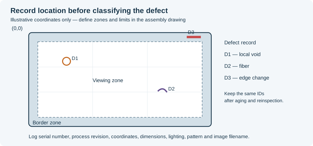
Schematic inspection record; the positions and defect sizes are illustrative.
Define the coordinate origin in the drawing, such as the top-left corner viewed from the front. Divide the active area and border into agreed zones. Log each defect with an ID so the same location can be revisited after environmental testing.
Useful fields include assembly serial number, adhesive lot, cover and LCD revisions, process recipe, operator or station, inspection time, defect coordinates, measured size, image filename, and disposition. Photograph a scale or use calibrated imaging when dimensions decide acceptance.
Keep a wide image for location and a close image for morphology. Fixed exposure and white balance make comparisons more meaningful. Do not digitally enhance a defect photo without retaining the original and identifying the enhancement.
Agree acceptance rules before pilot production
“No visible bubbles” sounds clear until one inspector uses a magnifier and another checks from half a metre away. Write the actual method:
- Display on/off conditions and test patterns.
- Room illumination and inspection light geometry.
- Viewing distance, angle range, and observation time.
- Whether magnification is diagnostic or part of acceptance.
- Zone-specific size, count, spacing, and edge limits.
- Rules for clusters and defects crossing a zone boundary.
- Functional criteria for touch, luminance, and image uniformity.
A small particle over a critical numeric readout may matter more than a larger mark hidden beneath a bezel. Where customer tasks are location dependent, use those tasks in the specification.
For a new custom stack, put these limits into the custom TFT LCD qualification requirements before tooling and sample approval. Otherwise, cosmetic yield becomes a negotiation after the parts have already been made.
Recheck after the mechanisms have had time to develop
Immediate inspection catches trapped air and visible contamination. Delayed inspection can reveal poor wet-out, outgassing, edge movement, or cure-related stress.
Use the material supplier’s conditioning requirements, then select environmental exposures from the product specification. Temperature cycling, humidity, and UV may be relevant, but the severity and duration must match the construction and use case. A test borrowed from an unrelated product can produce either false confidence or unnecessary failures.
After each stage, return to the same drive settings, thermal state, lighting, and mapped locations. Record new defects separately from growth of an existing defect. Keep the edge seal and black-print boundary in view; many failures begin there.
The OCA film and OCR resin process comparison helps connect defect patterns with lamination pressure, flow, gap control, curing, and substrate compatibility.
Turn the defect pattern into a process question
| Repeating observation | Investigation to prioritize |
|---|---|
| Bubbles follow the printed border | Ink-step coverage, gap, wet-out, cure access |
| Particles collect along one edge | Handling, liner removal, airflow, cleaning |
| Mura aligns with supports | Fixture flatness, mounting preload, lamination force |
| Bubbles develop during heat exposure | Outgassing, moisture, cure state, material compatibility |
| Defects repeat at one machine coordinate | Tooling surface, dispense path, alignment fixture |
These are hypotheses to test, not proof of cause. Change one process variable at a time, retain failed samples where practical, and compare results across material lots.
For optical context, check display haze and image-clarity measurements as well. A clean bond can still have unacceptable diffuse scattering or fine-detail loss.
What an approval record should contain
Release a stack only when the record links the approved drawing, materials, process window, inspection method, boundary samples, and reliability evidence. Add touch testing after bonding: a visually acceptable adhesive interface can still change the capacitive stack enough to require tuning.
Keep at least one reference assembly and representative images of accepted and rejected conditions. Revisit them when a polarizer, adhesive, ink, lens, or lamination recipe changes. The point of inspection is to make the next build more predictable, and that requires evidence the production team can reproduce.