I2C vs SPI vs USB Touch Interfaces: Integration Trade-Offs
Compare I2C, SPI, and USB touchscreen interfaces by report bandwidth, latency, drivers, wiring, power states, firmware updates, and industrial integration needs.
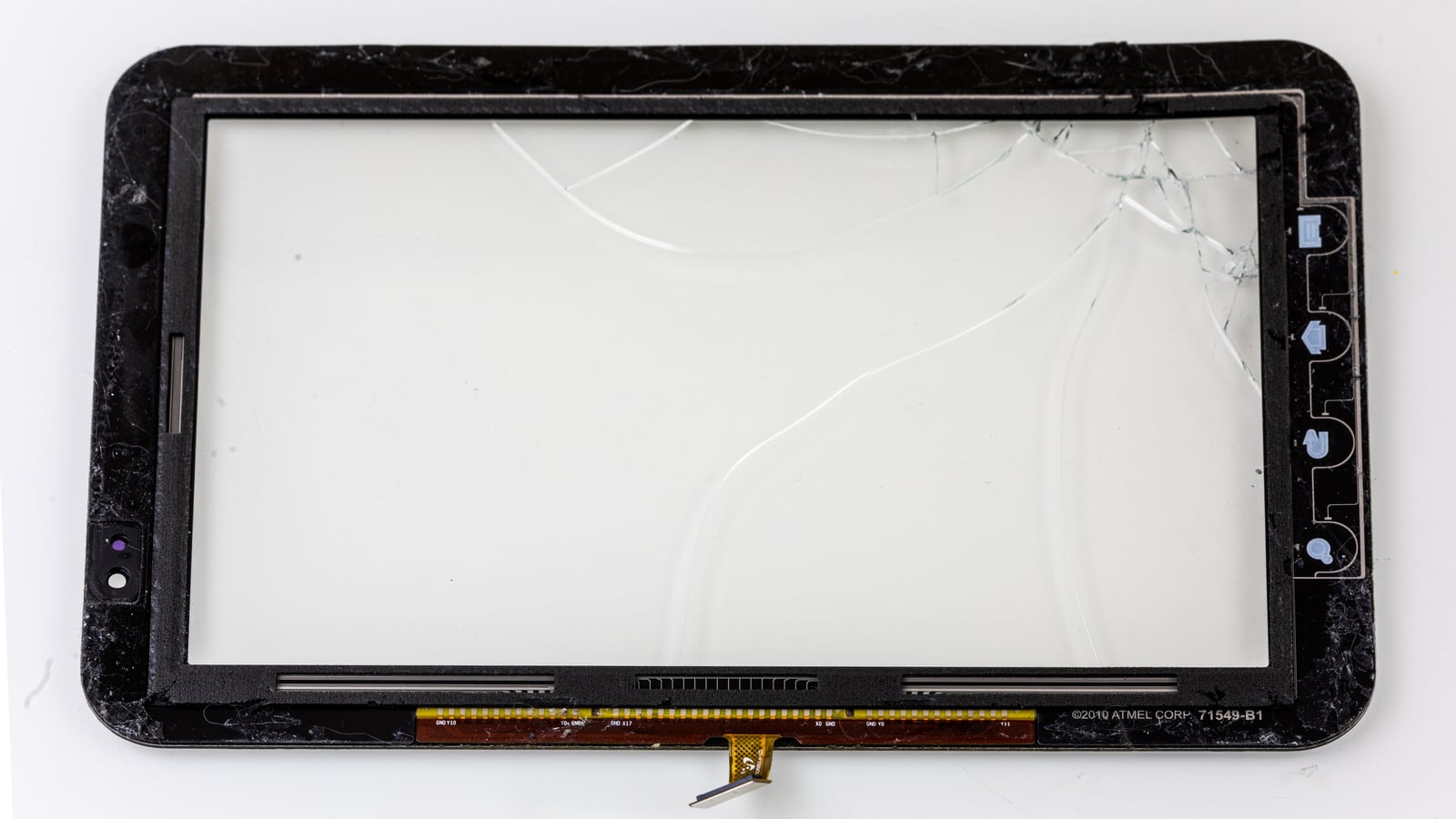
Choosing the touch interface is a host-integration decision, not a choice of touch sensitivity. The controller detects fingers; I2C, SPI, or USB transports reports to the host. A fast bus can still feel slow when scanning, filtering, scheduling, or application rendering adds delay.
The right comparison begins with the released controller and operating system. Check which interface modes the exact part and firmware support, then evaluate the wiring, driver, power states, diagnostic access, and update path as one system.
Photograph: © Raimond Spekking / CC BY-SA 4.0, via Wikimedia Commons. Resized and padded; the adapted photo retains the same license. The pictured assembly illustrates touch-panel construction, not support for all three interfaces.

First separate touch data from display video
A display may use MIPI DSI or LVDS for pixels while its touch controller uses I2C or USB. These are independent links with different bandwidth, startup, and grounding requirements. A working LCD image does not prove the touch path is correctly configured.
The touch controller generally converts sensor measurements into contact reports. Those reports may contain coordinates, contact IDs, status, pressure-like estimates, area, gestures, and diagnostic fields. Their format depends on the controller and protocol.
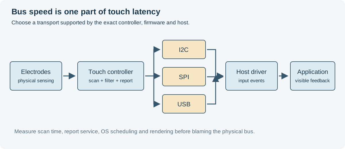
If the controller is supplied as part of a custom module, freeze its interface, voltage, connector, firmware, report format, and update procedure in the custom LCD touch-interface specification. “I2C touch supported” leaves too many integration details open.
How the three options compare
| Area | I2C | SPI | USB |
|---|---|---|---|
| Signal arrangement | SDA/SCL, often interrupt and reset | Clock, chip select, data lines, often interrupt/reset | USB data pair, power, and implementation-specific control |
| Typical integration | Short internal connection | Short internal connection with dedicated host support | Host-oriented module or serviceable subsystem |
| Electrical concern | Pull-ups, capacitance, voltage, rise time | Edge rate, timing, chip select, return paths | Controlled routing, grounding, ESD, power and connector behavior |
| Software question | Native protocol or HID over I2C? | Vendor protocol or a supported HID SPI implementation? | Correct HID reports, enumeration, driver and wake behavior? |
| Main advantage | Few bus lines and broad embedded support | Flexible transfer scheduling and potential throughput | Standard host infrastructure and convenient enumeration |
These are tendencies, not interchangeability rules. An adapter board may add a bridge, changing cost, latency, startup, and firmware responsibility.
I2C: simple wiring with electrical limits
I2C commonly suits a controller near the processor or connected by a short internal flex. Addressing allows multiple targets on the bus, though shared traffic can affect report service time.
NXP’s I2C-bus specification defines mode-dependent timing and electrical requirements. The supported rate is the intersection of the host, touch controller, pull-ups, bus capacitance, and physical interconnect. A higher software clock setting does not make a marginal rise time acceptable.
Confirm bus voltage, interrupt polarity, reset behavior, address, and powered-off pin states. If one target holds SDA low after a disturbed transaction, the host needs a recovery strategy appropriate to the controller. Include recovery in validation rather than discovering it after an ESD test.
HID over I2C is a specific protocol and enumeration model. A controller with a proprietary I2C register interface does not become HID-compatible merely because it uses the same wires.
SPI: useful throughput when the host stack supports it
SPI can provide higher practical throughput for large reports or diagnostic frames, depending on the controller and host. It also needs more signals and attention to chip-select framing, clock mode, setup/hold, and transfer sequencing.
Check whether the host can perform the required transaction sizes and delays. Some peripherals tolerate continuous chip select across a command and response; others require boundaries or ready indications. DMA behavior and driver locking can matter more than the nominal clock rate.
A controller advertised with SPI does not guarantee a ready driver for your OS. Confirm the exact protocol, supported firmware, and update tool before laying out the board. Linux’s touch host controller documentation provides one concrete example of how supported HID SPI/I2C transports depend on platform configuration and device information.
USB: convenient integration still needs validation
USB HID touch modules can simplify integration with supported hosts. Enumeration, descriptors, report layout, coordinate ranges, and multi-touch handling still need checking. “Driverless” is shorthand for using an OS-provided driver; it does not mean every feature and power state works automatically.
Review power budgets, suspend current, remote wake if required, cable and connector grounding, and behavior after disconnect or brownout. An internally connected USB device may not be designed for field hot plugging, so qualify the actual service procedure.
If the module uses an I2C-to-USB bridge, identify who owns bridge firmware and descriptor changes. A bridge can make host integration easier while making production updates or diagnostics more complex.
Calculate the data requirement before choosing speed
Assume an illustrative report has a 4-byte header and 10 contacts of 8 bytes each. At 100 reports per second:
Report size = 4 + 10 × 8 = 84 bytes
Payload rate = 84 × 100 = 8,400 bytes/s
For an I2C transfer, nine clock cycles per byte gives a payload-only lower bound of 756 µs at 1 MHz or 1.89 ms at 400 kHz. Address phases, register selection, repeated starts, controller delays, retries, and other bus users add time. These numbers are an example, not the report size of the photographed panel.
Normal contact reports can be modest, while raw diagnostic frames are much larger. Define whether diagnostics must run at full rate during operation or only during development.
Measure end-to-end latency
The user experiences a chain:
Finger contact → scan → filtering → report ready → host read
→ OS input processing → application → next visible frame
Measure stages where possible. An interrupt-to-read timestamp isolates host service delay. A controlled touch stimulus and high-speed camera can help characterize the complete system, provided the method and uncertainty are documented.
Do not equate bus rate with touch report rate or display refresh. A controller may scan faster than it reports, and an application can wait another frame before showing feedback.
Multi-touch behavior belongs in the acceptance test
Verify stable contact IDs, simultaneous touches, lift-off, edge behavior, and recovery after a missed report. Linux’s multi-touch input protocol explains how identifiable contacts and slots are represented in the input subsystem. Transport correctness is only one part of delivering those events reliably.
Use the final orientation and coordinate mapping. A working single-finger cursor can hide swapped axes or incorrect multi-contact release behavior.
Bring-up and lifecycle questions
Ask these before committing the interface:
- Is there a maintained driver for the exact controller, firmware, and OS version?
- How are configuration and firmware versions read and verified?
- Can updates recover after interrupted power?
- What does the interrupt mean, and when is a report acknowledged?
- How do suspend, wake, reset, and brownout affect pending contacts?
- Can factory diagnostics run through the production connection?
- Who controls protocol changes and bridge firmware?
Pair that review with touch and display cable requirements and PCAP validation under gloves, water, and interference.
For a compact embedded host with a short internal connection and mature support, I2C may be the easiest release path. SPI is attractive when the controller and host software justify its additional signals. USB often suits a more modular host architecture. Choose the path you can validate and maintain through boot, normal use, faults, updates, and service.