How to Evaluate Touch Performance on Industrial IPS Displays
A practical checklist for evaluating touch performance on industrial IPS displays, including gloves, water, cover glass, EMI, grounding, firmware tuning, and production repeatability.
Touch performance is easy to underestimate. A sample display may respond well in the office, then behave poorly after it is installed behind thicker cover glass, placed inside a metal enclosure, connected to a noisy power supply, or used by an operator wearing gloves.
For industrial IPS displays, the question is not only whether touch works. The question is whether it works reliably under the conditions the product will actually see.
This article focuses mainly on projected capacitive touch, because PCAP is common in modern HMIs. Many of the same evaluation habits also apply to resistive touch and other touch technologies.
Test with the final cover glass
Cover glass changes touch behavior. Thickness, material, ink border, air gap, bonding adhesive, and sensor geometry all affect signal strength. A touch panel that works through thin glass may become less responsive through thicker vandal-resistant cover glass.
If the product will use custom cover glass, do not approve touch performance from a bare sensor. Build a stack with the intended glass thickness, decoration, adhesive, and LCD module. If optical bonding is planned, test the bonded stack. If an air gap is planned, test the air gap.
Also check edge performance. Some products have wide printed borders or metal bezels that affect touch near the edges. If the UI places buttons near the corners, those areas deserve special attention.
Define glove requirements clearly
“Glove support” is not a single requirement. Thin nitrile gloves, leather work gloves, winter gloves, and coated industrial gloves behave differently. Some are easy for PCAP controllers to detect. Others need higher sensitivity or a different sensor design.
Before tuning the controller, define which gloves must work. Then test with those exact glove types. Avoid approving a vague glove claim based on one convenient sample.
There is also a trade-off. Increasing sensitivity for glove operation can make the system more vulnerable to noise, water, or false touches. The right tuning depends on the product. A medical cart, outdoor kiosk, and factory machine panel may need different behavior.
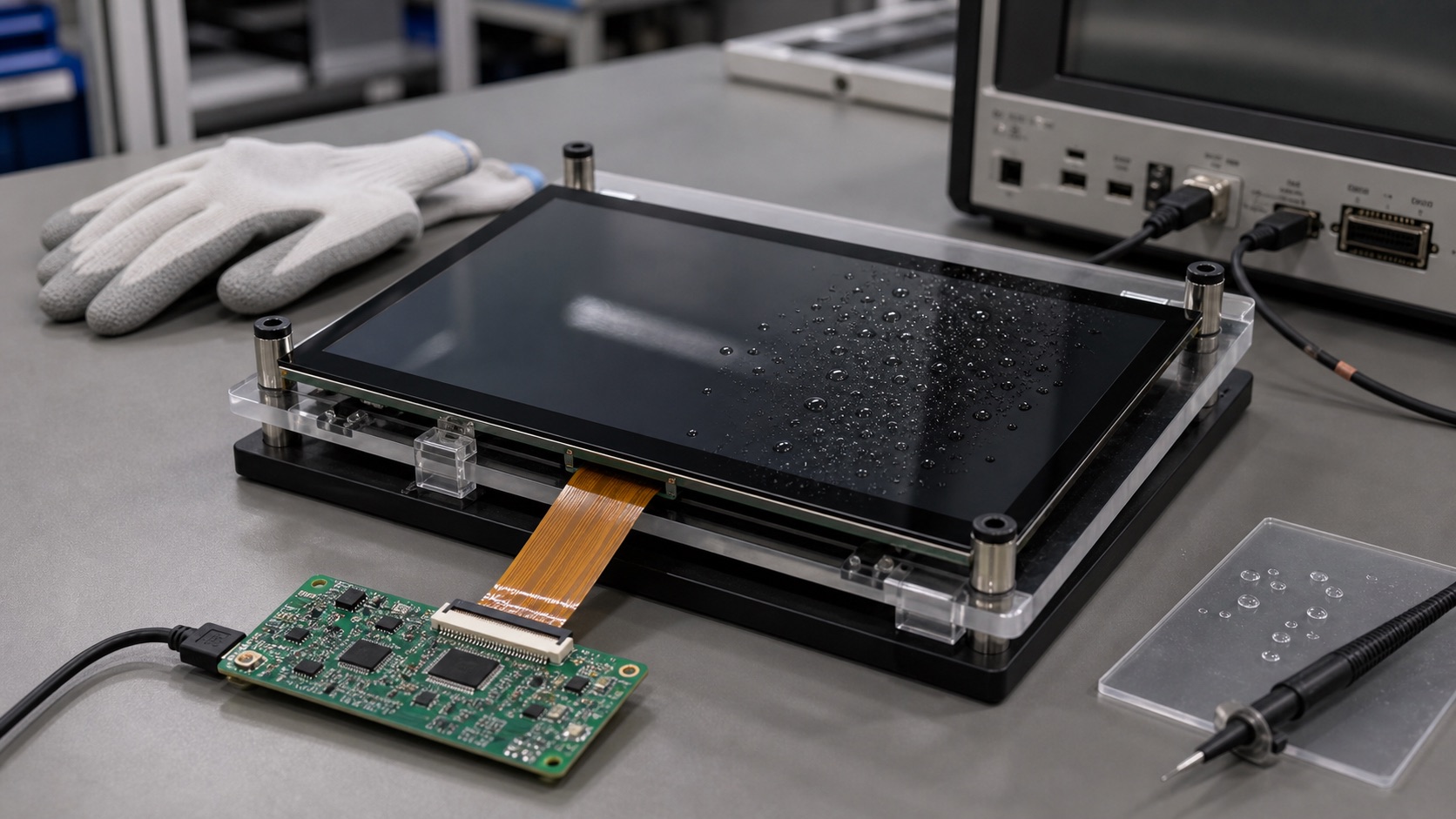
Test wet-finger and water behavior
Water is one of the hardest touch conditions. Droplets can create false touches, block touches, or cause the controller to track incorrectly. Outdoor displays, cleaning-intensive equipment, and food-processing environments should all consider water behavior.
Do not test water only by lightly touching the screen with a damp finger. Try realistic conditions: droplets on the surface, wiping motion, wet gloves, water near the bezel, and cleaning fluid if relevant. Check whether the controller rejects water, tracks through water, or enters a special wet mode.
The correct behavior depends on the application. Some products should ignore touches when heavy water is present. Others need limited operation in rain. Define the expected behavior before testing, or the result will be subjective.
Check EMI and grounding with the real enclosure
PCAP controllers measure small capacitance changes, so grounding and electrical noise matter. A touch system that works on a bench can behave differently inside the final enclosure.
Switching power supplies, motors, radios, long cables, and metal frames can all affect touch stability. Poor grounding can cause missed touches or false touches. A floating system may behave differently when the user touches it while standing on a conductive floor or holding a grounded tool.
For evaluation, test the touch panel with the intended power supply, display backlight setting, enclosure, cable routing, and grounding method. Run ESD and EMI tests while monitoring touch behavior, not only while checking whether the product resets.
Evaluate the user interface, not just raw touch points
Touch performance should be judged with the real UI. A controller may report touch points accurately, but the product may still feel poor if buttons are too small, edge targets are hard to hit, or the UI does not handle accidental touches well.
Industrial users may be wearing gloves, moving quickly, or looking at the display from an angle. Buttons should have enough size and spacing. Critical actions should avoid being too close to edges or frequently touched areas. The display’s viewing angle and touch ergonomics should be considered together.
It is useful to let people outside the engineering team try the interface. Operators, assembly workers, and service technicians often notice touch problems that engineers miss because they interact with the product differently.
Watch startup, sleep, and recovery behavior
Touch evaluation should include power states. Test cold boot, warm restart, sleep and resume, display dimming, controller reset, and cable reconnect if the design allows service replacement. Some systems work well after a clean boot but fail after repeated suspend cycles.
Baseline tracking is especially important. A PCAP controller continuously adapts to environmental conditions. Temperature, humidity, water, gloves, and grounding can shift the baseline. If the firmware handles this poorly, the touch panel may become less responsive over time or after a power event.
Keep touch controller firmware and tuning files under version control. A small tuning change can affect field behavior, so it should be tied to a specific hardware stack.
Check production variation
One good sample is not enough. Cover glass thickness, adhesive thickness, sensor alignment, FPC routing, grounding, and controller components can vary in production. If the touch margin is narrow, production variation will expose it.
Build several samples if possible. Test across temperature, humidity, and expected operating modes. Keep a golden sample and define incoming inspection criteria. If the supplier changes touch IC, sensor pattern, adhesive, or firmware, require a review before accepting the change.
This is where EEAT-style content becomes real in engineering: experience matters because touch failures are often not visible in a datasheet. They appear when materials, firmware, assembly, and users interact.
Practical approval criteria
Before approving an industrial IPS display with touch, confirm the following:
- Touch works through the final cover glass and bonding stack.
- Supported glove types are defined and tested.
- Wet behavior is documented.
- EMI and ESD testing includes touch monitoring.
- The real UI is comfortable to operate.
- Sleep, resume, dimming, and reset behavior are stable.
- Controller tuning files are controlled.
- Supplier change control covers touch hardware and firmware.
Touch is the part of the display system that users physically judge. If it feels unreliable, the whole product feels unreliable. A disciplined evaluation process is the best way to avoid that outcome.
Related Engineering Context
For a deeper technical treatment of controller tuning and grounding, see the PCAP touch panel design guide. If the project is still deciding between touch technologies, the capacitive vs resistive touch guide gives a useful comparison before committing to the front stack.