Why Display Interface Decisions Should Happen Before Enclosure Design
A practical discussion of why LVDS, MIPI DSI, eDP, HDMI, and other display interface decisions should be made before mechanical enclosure design is locked.
Display interface decisions often look like electrical engineering details, so teams sometimes postpone them until after the enclosure concept is mostly fixed. That can be an expensive mistake. The interface affects cable length, connector position, board placement, EMI behavior, firmware support, power sequencing, service access, and even the direction the display FPC exits the module.
In embedded products, the display is not just a screen. It is a mechanical and electrical subsystem. If the interface is chosen too late, the team may discover that the cable path is too long, the connector is blocked, the processor does not support the panel cleanly, or the EMI margin is weak.
The better approach is to decide the display interface early enough that electrical and mechanical design can grow around the same assumptions.
Cable path is a mechanical decision
Every display interface has a practical cable limit. LVDS can handle longer internal runs when designed correctly. MIPI DSI usually wants a short FPC close to the processor. eDP supports high resolution well, but still needs controlled high-speed routing. HDMI is convenient for external connections but can be bulky and less ideal for internal embedded assemblies.
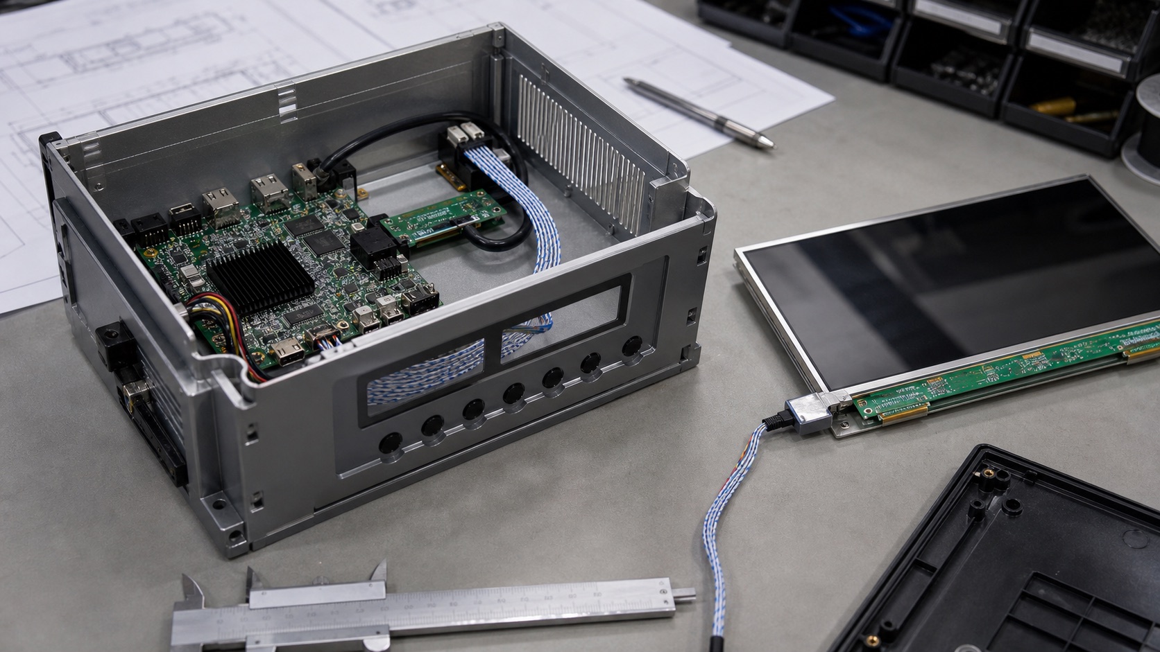
The enclosure decides where the display sits, where the main board sits, and how the cable must bend. If the enclosure is designed before the interface is confirmed, the cable path may become unrealistic. A short MIPI DSI connection can turn into a long, fragile FPC route. A connector may land under a mounting boss. A service technician may need to bend a cable sharply just to assemble the unit.
Cable routing should be reviewed in the same meeting as display selection. The team should check length, bend radius, shielding, connector retention, strain relief, and assembly order. A display that works on a bench cable is not proof that it will work in the final enclosure.
Connector location can drive the whole internal layout
Panel drawings show more than outline size. They show active area, viewing area, mounting features, component height, FPC location, and connector direction. These details matter.
If the FPC exits from the wrong side, the main board may need to move. If the connector is too close to the enclosure wall, the cable may be hard to insert. If the cable crosses a noisy power section, EMI risk increases. If the FPC is trapped behind adhesive or a bracket, repair becomes difficult.
Before locking enclosure design, place the real panel drawing into the mechanical model. Include the FPC and connector, not only the glass outline. Then ask a simple question: can this be assembled repeatedly by production workers without damaging the display?
Firmware support should be checked before industrial design is frozen
Some display interfaces are more software-dependent than others. MIPI DSI panels often need specific initialization commands. eDP requires link training and platform support. LVDS needs correct timing and mapping. HDMI depends on mode detection and sometimes EDID behavior.
If the processor platform does not support the chosen panel cleanly, the mechanical design may need to change to support a different display. That is painful if the enclosure is already tooled.
Engineering teams should bring up a candidate display on the intended platform early. It does not need to be in the final enclosure. The goal is to confirm that the display can boot, show the correct colors, dim properly, sleep and resume, rotate if needed, and recover from power events.
EMI risk depends on both interface and enclosure
High-speed display signals do not exist in isolation. Cable length, shielding, ground reference, metal enclosure structure, board stack-up, and nearby power electronics all affect EMI behavior.
LVDS is generally robust, but poor cable shielding or bad grounding can still create problems. MIPI DSI has low pin count and high speed, so routing discipline matters. eDP can be reliable, but high-speed lanes and AUX communication need proper layout. HDMI can radiate if cable and connector design are weak.
The enclosure can help or hurt. A metal chassis may provide shielding, but it can also create grounding decisions. A plastic enclosure may need more cable shielding. A hinged display section may create repeated flex and changing ground paths.
EMI review should happen before the mechanical design is final. It is much easier to add a better cable path, shield connection, ground spring, or board position early than after tooling.
Power sequencing needs physical space
Display modules often require logic power, reset, interface signals, backlight enable, and touch power to follow a defined sequence. Backlight drivers may need inductors, current-setting parts, thermal space, and fault handling. Touch controllers may need clean routing and grounding.
If the enclosure forces the main board into a small corner, there may not be enough room for the right power architecture. Teams then try to solve hardware constraints with firmware delays, which may not be reliable.
The display power system should be reviewed early with the mechanical layout. Check board area, heat, connector current, inrush behavior, and cable voltage drop. A display that lights up in the lab can still fail in a product if the backlight supply is marginal.
Service and manufacturing are part of the interface decision
A display interface also affects production and service. Some connectors are easy to insert and inspect. Others are small, delicate, or hidden. Some cables tolerate repeated handling. Others are intended for one-time assembly.
If the product is serviced in the field, connector access matters. If the display is bonded to a front cover, rework may be expensive. If the cable is trapped under a board, replacing a display may require too much disassembly.
Manufacturing engineers should review the display interface and cable path before the enclosure is released. Their questions are practical: Can operators connect it quickly? Can inspection verify seating? Can the cable be damaged during assembly? Can the unit be repaired without replacing unnecessary parts?
A simple early review saves redesigns
The display interface should be chosen with the processor, panel, cable, enclosure, firmware, and manufacturing process in mind. That sounds like more work, but it prevents late-stage surprises.
Before enclosure design is locked, confirm the display interface, cable route, connector position, power sequence, firmware support, EMI approach, and assembly process. This does not require a perfect final prototype. It requires the right people looking at the same assumptions early.
In embedded design, the display is where users judge the product. It is also where many engineering disciplines meet. Treating the interface as an early system decision makes the whole product easier to build.
Related Engineering Context
For a technical comparison of LVDS, MIPI DSI, eDP, and HDMI, use the display interfaces guide as the main reference. If the product uses a longer internal cable or noisy installation environment, the LVDS display panel design guide is especially relevant.