Display Connectors and Cables: FPC, Board-to-Board, and Wire Harnesses
Choose display FPC, FFC, board-to-board, micro-coax, and wire harnesses using pitch, pinout, impedance, retention, flex life, current, and service needs.
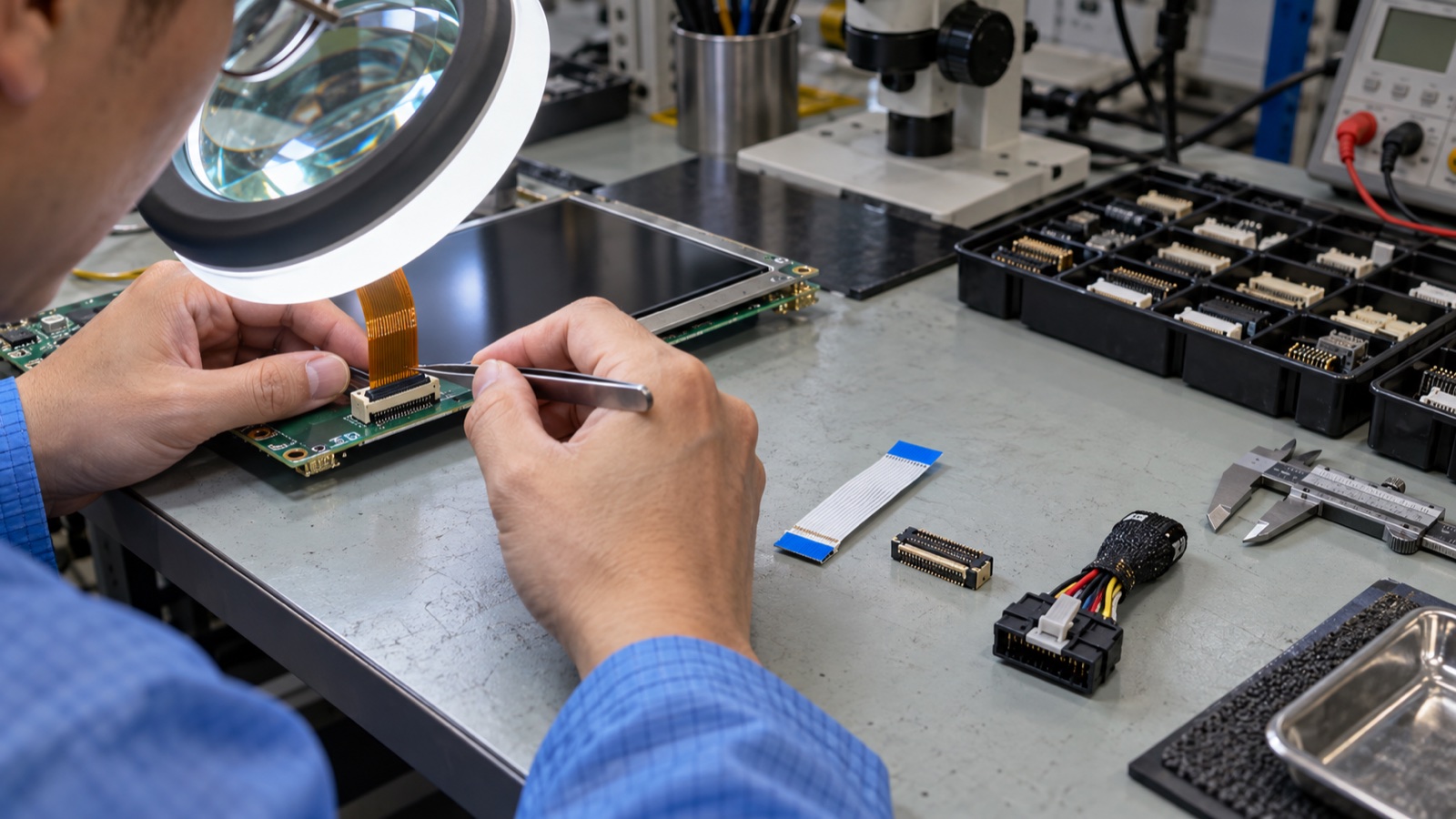
Display cable failures rarely begin with a dramatic electrical mistake. More often, an FPC is inserted upside down, a latch is damaged during rework, a bend moves too close to the stiffener, a wire harness carries backlight current through an undersized contact, or a high-speed pair loses its return path at the connector.
The display may work on the first prototype and fail after assembly, vibration, service, or a supplier substitution.
Connector choice should be made from the complete signal, mechanical, manufacturing, and service requirements. Contact count and pitch are only the first two rows of that specification.
Start by naming the interconnect correctly
The terms are related but not interchangeable.
FPC
A flexible printed circuit is manufactured with patterned copper on a flexible dielectric. It can include controlled-impedance pairs, ground layers, shields, stiffeners, components, and custom shapes. The display’s attached tail is usually an FPC.
FFC
A flat flexible cable typically uses parallel flat conductors laminated in plastic film. Standard pitches and conductor counts make it economical for simple board-to-board or board-to-display connections. Some high-speed and shielded versions are available.
Board-to-board mezzanine connector
Two connector halves mate PCBs or rigid-flex assemblies directly. This provides compact, repeatable alignment but requires careful tolerance control and can transmit mechanical load into the display board.
Wire harness
Discrete wires, twisted pairs, shielded pairs, or micro-coax are terminated into housings. Harnesses suit longer routes, higher current, serviceable modules, and three-dimensional paths better than many flat cables.
The correct category follows the assembly architecture. Do not force a delicate panel tail to behave like a service cable.
Build a pin-level requirement before selecting a series
List every contact and classify it:
- High-speed differential data.
- Single-ended clock or data.
- Power rail and maximum current.
- Backlight supply and return.
- Reset, enable, PWM, interrupt, or I²C.
- Ground/return contacts.
- Shield termination.
- Reserved or no-connect pins.
Then add voltage, current, edge rate, impedance, direction, powered-off state, and ESD exposure.
A 30-position, 0.5 mm connector does not automatically replace another 30-position, 0.5 mm part. Contact side, pin numbering, actuator type, FPC thickness, stiffener length, insertion depth, housing height, and footprint can all differ.
Contact orientation causes expensive mistakes
FPC/FFC connectors can use top contact, bottom contact, or dual contact. Cable conductors can face the same or opposite sides at their two ends. A cable that looks correct in a 2D drawing can reverse every pin after folding.
Release documentation should show:
- Connector view and pin 1.
- Contact side at both ends.
- Cable fold direction.
- Exposed-conductor orientation.
- Stiffener side and thickness.
- Finished cable length reference.
- Assembly photograph.
Perform a continuity check on first articles. Do not rely on color or the apparent direction of printed labels.
Pitch and circuit count affect manufacturability
Fine pitch reduces area but narrows tolerance and contamination margin. Compare:
- 0.2/0.25 mm for highly space-constrained products.
- 0.3/0.4 mm for compact high-density designs.
- 0.5 mm as a common embedded-display choice.
- 1.0 mm and above where robustness and easier handling matter.
Smaller is not always better. Operators wearing gloves, low-volume manual assembly, field service, dust exposure, and repeated insertion may justify a larger connector or positive-latching harness.
Molex lists FFC/FPC product families from 0.20 to 2.00 mm pitch with many actuator styles. That breadth is useful because pitch should follow assembly and environment, not fashion.
Zero-insertion-force still requires process control
ZIF connectors reduce insertion force by opening an actuator before the cable is inserted. Typical damage comes from:
- Inserting without opening the latch.
- Lifting the actuator beyond its allowed angle.
- Closing it before the cable reaches the insertion stop.
- Pulling the cable without releasing the latch.
- Applying side load through an immediate bend.
- Reusing a connector beyond its mating-cycle rating.
Add clear work instructions, magnification where needed, and a go/no-go visual reference. If the connector is not intended for repeated service, keep it away from field-replaceable boundaries.
High-speed signals need an interconnect channel, not just contacts
LVDS, eDP, MIPI D-PHY, HDMI, and other fast links depend on controlled impedance, low loss, pair balance, and continuous return current.
Review the whole channel:
transmitter package -> PCB -> connector -> cable/FPC -> connector -> PCB -> receiver
At the connector, check:
- Differential impedance.
- Insertion and return loss.
- Intra-pair skew.
- Inter-pair skew.
- Near/far-end crosstalk.
- Ground contact placement.
- Reference-plane transition.
- Shield termination.
Hirose’s high-speed FPC literature uses GSSG arrangements and publishes impedance/eye-pattern data for specific connector series. That is much stronger evidence than a generic claim that a connector is “high speed.”
Use the frequency content and rise time of the actual interface. A connector proven for one standard, stackup, and FPC does not guarantee performance with a different cable geometry.
Ground pins are part of the signal path
High-speed return current takes the path of lowest impedance, usually close to the signal. If a differential pair crosses a connector without nearby grounds, common-mode energy and emissions can increase.
Allocate grounds intentionally:
- Beside or around differential pairs where the connector system recommends it.
- Adjacent to fast single-ended clocks.
- With enough contacts for backlight and logic return current.
- At shield ends according to the EMC strategy.
Do not combine a noisy LED-current return with a sensitive high-speed reference through one narrow contact if the pinout can avoid it.
Power contacts need derating
Connector current ratings are measured under stated conditions. Temperature rise depends on contact resistance, number of loaded contacts, adjacent current-carrying contacts, copper area, ambient temperature, and enclosure airflow.
For backlight and panel power:
- Calculate maximum current at minimum supply voltage.
- Include startup and inrush.
- Use multiple contacts where permitted.
- Allocate matching return contacts.
- Check voltage drop at hot and aged contact resistance.
- Verify connector and cable temperature rise.
- Consider short-circuit and mis-mating behavior.
Gold plating, tin plating, contact force, and cycle count affect long-term resistance. The most economical finish depends on environment and mating expectations.
Bend radius is only one flex requirement
An FPC can tolerate a static bend and still fail under repeated motion. Define whether the cable experiences:
- One-time installation bend.
- Occasional service flex.
- Continuous dynamic flex.
- Torsion.
- Folding near a stiffener.
- Vibration-driven micro-motion.
Keep the bend away from the connector exit and the transition between stiffened and flexible regions. Avoid sharp folds across copper traces. Maintain clearance from enclosure edges, screw bosses, heat sinks, and adhesive squeeze-out.
The cable supplier should define minimum static and dynamic bend radii for the exact layer structure and copper type. A rule based only on overall thickness may be too optimistic for a multilayer, shielded FPC.
Strain relief should protect the termination
Cable retention is not strain relief by itself. A harness can be latched yet transmit vibration into crimp contacts. An FPC can be locked yet peel upward from an angled route.
Use clips, guides, adhesive fixtures, foam, or tie points where appropriate, while avoiding:
- Compression on the active display area.
- Rubbing against sharp metal.
- Heat near adhesive anchors.
- A fixture that forces the cable below its bend radius.
- Service steps that pull on the panel tail.
Review tolerance stack-up. A clip that looks relaxed in nominal CAD may preload the cable at one mechanical extreme.
Board-to-board connectors need alignment strategy
Mezzanine connectors create a neat assembly but can be unforgiving. Check:
- X/Y and angular misalignment allowance.
- Stacking-height tolerance.
- Mating force and board deflection.
- Guide posts or floating features.
- Connector coplanarity after reflow.
- Assembly visibility.
- Unmating access.
- Shock/vibration retention.
Do not use the display PCB and glass as a lever to mate the connector. The fixture should apply force through supported rigid areas.
Wire harnesses suit distance and service
A harness becomes attractive when the display is remote from the main board, crosses hinges or enclosure sections, carries meaningful current, or must be replaceable.
Options include:
- Twisted pairs for LVDS-like signals.
- Micro-coax assemblies for high-speed density.
- Shielded multi-pair cable.
- Separate power and data harnesses.
- Positive-lock wire-to-board housings.
Harness design adds crimp tooling, pull-force inspection, wire identification, shield termination, and routing space. Connector coding and polarization become important when similar harnesses coexist.
Mechanical choices affect EMI and signal integrity
A cable that passes on an open bench can fail after routing near a motor drive, DC/DC inductor, backlight node, or grounded chassis edge. The early display cable and enclosure review should reserve a clean path before internal volume disappears.
During validation, test:
- Production cable length and vendor.
- Minimum bend radius and worst route.
- Shield/ground attachment as assembled.
- Maximum display bandwidth and high-transition patterns.
- Backlight PWM at multiple brightness levels.
- ESD applied to the cover, bezel, and service connector.
- Nearby radio and motor activity.
If changing the cable fixes an image problem, the root cause may be impedance, ground return, coupling, or connector assembly—not the panel itself.
Touch and display can share mechanical risk
Touch-controller I²C/USB, interrupt, reset, and ground may travel beside display data and backlight power. A combined tail saves connectors but couples procurement and service decisions.
The industrial PCAP integration checklist should identify grounding, shielding, cable length, noise sources, and ESD paths. Ensure touch ground does not depend on an unreliable shield tab or chassis contact.
Incoming inspection should be specific
For cable and connector assemblies, inspect:
- Correct part/revision and pin count.
- Contact side and pin-1 marking.
- FPC/FFC width, pitch, and thickness.
- Stiffener dimensions.
- Exposed copper length and finish.
- Latch condition.
- Crimp height and pull force for harnesses.
- Shield termination.
- Continuity and shorts.
- Cosmetic damage, contamination, and sharp creases.
Keep approved samples and photographs. A cable can be electrically correct but mechanically incompatible with the production assembly.
Qualification tests worth running
| Risk | Test |
|---|---|
| Assembly damage | Repeated controlled build/rework trial |
| Intermittent contact | Vibration while monitoring link/errors |
| Cable fatigue | Flex test matching motion and bend radius |
| Contact resistance | Four-wire or specified low-level measurement |
| Power heating | Maximum current at hot ambient |
| High-speed margin | Eye/TDR or system BER/error monitoring |
| ESD coupling | System-level discharge with final enclosure |
| Retention | Pull/unmate force and latch inspection |
| Environment | Temperature/humidity cycling and recovery |
For a compact module such as a 4-inch square IPS display, the short FPC and fine-pitch connector may dominate assembly yield even when electrical bandwidth is modest.
Release checklist
- Connector manufacturer and full part number are frozen.
- Mating part, cable, contacts, and tooling are specified.
- Contact side and pin numbering are shown graphically.
- Power/current and return allocation are reviewed.
- High-speed impedance and ground pattern are supported by data.
- Bend, strain relief, and tolerance extremes are modeled.
- Assembly and service cycle counts are defined.
- Work instructions prevent latch and insertion damage.
- Production cable is included in EMI, ESD, vibration, and thermal tests.
- Approved alternatives are qualified, not assumed equivalent.
FAQ
Are FPC and FFC the same?
No. FPC is a patterned flexible circuit that can be highly customized; FFC is commonly a laminated parallel-conductor cable. Both can mate with similar connector families.
Can any 0.5 mm, 30-pin connector replace another?
No. Footprint, contact side, FPC thickness, actuator, pin numbering, insertion depth, height, current, and high-speed performance can differ.
How many times can a ZIF connector be reworked?
Use the manufacturer’s mating-cycle rating and production process limits. Many compact connectors are not intended for frequent field service.
Should a display cable shield be grounded at both ends?
It depends on frequency, chassis architecture, ESD path, and common-mode current. Define and test the termination rather than applying a universal one-end rule.
Technical references
- Hirose FH55/FH55M high-speed FPC connector data — publishes GSSG layout, differential impedance, and eye-pattern information.
- Molex FFC/FPC connector portfolio guidance — documents pitch, actuator, retention, temperature, and circuit-count options.
- Molex high-speed FFC/FPC cable guidance — discusses shielding, impedance, LVDS use, retention, and board-to-display interconnects.