Display Brightness Explained: Nits, Luminance, and Real-World Needs
Understand display brightness, nits, luminance, measurement conditions, outdoor readability, optical losses, dimming, heat, and application targets.
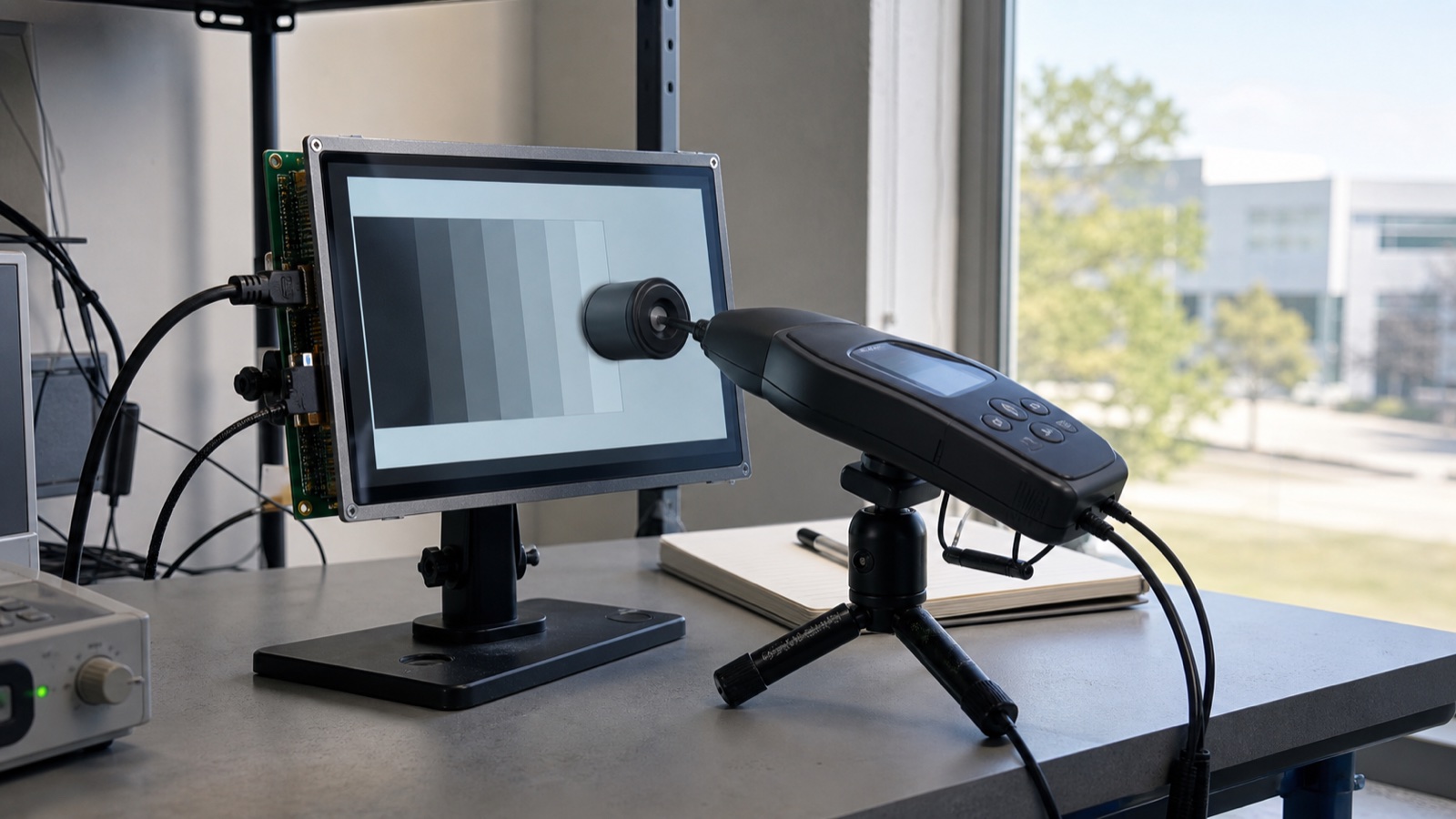
How bright should a display be? The short answer is: bright enough to preserve useful contrast in the real environment, but no brighter than the product can support thermally, electrically, and at night.
That answer is less convenient than choosing the largest number on a datasheet. It is also far more reliable. A 1000-nit bare LCD can become disappointing behind a reflective touch stack, while a carefully bonded 800-nit module can remain easier to read. Brightness is an emitted-light measurement. Readability is a system result.
What is a nit?
A nit is the informal name for one candela per square metre:
1 nit = 1 cd/m²
The formal optical quantity is luminance. It describes luminous intensity leaving a surface in a particular direction per unit projected area. Display datasheets and light meters commonly report it in cd/m²; product discussions usually say “nits.” Numerically, they are the same unit.
Luminance is not illuminance. Illuminance, measured in lux, describes light arriving at a surface. A display may emit 800 cd/m² while the front glass is exposed to thousands of lux from the surrounding environment. The two quantities cannot be converted with a single universal formula because geometry, direction, reflectance, and surface properties matter.
What the datasheet brightness number tells you
A panel luminance specification is useful only with its conditions. Check whether the value is:
- Minimum or typical.
- Measured at the center or averaged across several points.
- Recorded after a defined warm-up time.
- Measured at maximum backlight current or a nominal setting.
- Taken at room temperature.
- For the bare LCD module or a bonded touch assembly.
“1000 nits typical” does not promise that every production unit will ship at 1000 nits. It also does not tell you what the user will see after adding a touch sensor, cover glass, optical adhesive, anti-glare treatment, or automatic dimming.
For sourcing, ask for a minimum luminance at a defined current and temperature. For engineering, measure the final stack.
A practical starting range
The following ranges are useful for early architecture discussions, not as automatic pass/fail criteria:
| Use environment | Practical starting range | What usually decides the result |
|---|---|---|
| Controlled indoor room | 250–400 nits | UI contrast, viewing angle, low-level dimming |
| Factory floor or bright retail | 400–700 nits | Overhead reflections, mounting angle, dust |
| Near windows / bright indoor | 500–800 nits | Glass reflection and time of day |
| Shaded or intermittent outdoor use | 700–1000 nits | Optical bonding, surface treatment, sun angle |
| Direct-sun outdoor equipment | 1000–1500+ nits | Reflectance, thermal design, UI, duty cycle |
| Night vehicle or dark control room | Low minimum matters more | Smooth dimming, black level, glare to the user |
These bands overlap because “outdoor” is not one condition. An EV charger under a canopy, a handheld terminal used for five minutes at a time, and a marine screen facing open sky impose very different requirements.
The existing 7-inch 800-nit LVDS panel is a reasonable starting point for bright indoor and some shaded outdoor systems. A larger 15.6-inch 1000-nit panel may support outdoor-facing terminals, but its larger backlight and glass area also increase heat and reflection risk. The number alone does not approve either application.
Why the final assembly is dimmer than the panel
Every optical layer transmits less than 100 percent of the display light. A simplified estimate is:
Final white luminance ≈ panel luminance × transmission of each added layer
Assume a 1000-nit module sits behind a touch layer with 92% transmission and a cover treatment with 90% effective transmission. Ignoring other losses:
1000 × 0.92 × 0.90 ≈ 828 nits
This is a budget estimate, not a substitute for measurement. Real stacks include wavelength and angle effects, bonding interfaces, polarizers, printed borders, contamination, and sample variation. More importantly, transmission loss is only half of the story. The outer surfaces also reflect ambient light back toward the user.
Brightness does not cancel reflection
In a dark lab, a display’s white and black luminance may produce an impressive contrast ratio. Outdoors, reflected light is added to both. A useful simplified expression for ambient contrast is:
Ambient contrast ≈ (display white + reflected ambient light)
                   / (display black + reflected ambient light)
Suppose a display produces 800 cd/m² white and 0.8 cd/m² black, a static contrast ratio of 1000:1. If the front stack contributes an equivalent 40 cd/m² of reflected ambient luminance, the visible ratio becomes roughly:
(800 + 40) / (0.8 + 40) ≈ 20.6:1
The backlight did not become weaker. The black level was lifted by reflection. This is why reducing reflectance through stack design, optical bonding, anti-reflective treatment, enclosure angle, and surface cleanliness can be as valuable as adding more LED current.
For field evaluation, use the outdoor IPS readability test method rather than judging a bare sample under office lighting.
Brightness, power, heat, and lifetime are linked
Most transmissive TFT LCDs increase brightness by driving the LED backlight harder or by using a more efficient optical stack. Higher LED current normally increases power and heat. Temperature then affects LED output, backlight aging, liquid-crystal response, adhesives, touch electronics, and the rest of a sealed enclosure.
This creates a design loop:
- The environment requires more luminance.
- More luminance requires backlight power.
- Backlight power raises temperature.
- Higher temperature reduces lifetime margin and may reduce optical performance.
- Thermal derating or dimming changes the luminance available in the worst case.
Do not approve a high-brightness display only from its first five minutes at room temperature. Run it at the intended current inside a representative enclosure. Record ambient temperature, LED current, input power, LCD surface temperature, internal air temperature, and stabilized luminance.
Texas Instruments’ backlight guidance distinguishes analog current control from PWM-based dimming and notes the trade-offs between dimming methods. That matters because the driver and dimming architecture determine whether a display can move cleanly from noon brightness to a comfortable night setting—not just whether it can reach its maximum output.
Peak, full-screen, and sustained brightness are different
Consumer HDR specifications made this distinction visible, but the same measurement discipline is useful for embedded displays. A small white patch may reach a higher short-duration luminance than a full white screen held for several minutes. Thermal control, local dimming, driver limits, or firmware may reduce sustained output.
For an industrial HMI, a full-screen or large-area white UI can be realistic. Ask whether the quoted luminance is stable with that content and at the expected temperature. A brief peak value is not a suitable basis for an always-on control screen.
VESA’s current DisplayHDR criteria use separate small-patch, full-screen flash, and long-duration luminance tests. An industrial panel does not need DisplayHDR certification, but the test structure illustrates an important point: luminance numbers are meaningful only when image area and duration are stated.
How to measure display luminance consistently
A basic engineering check can be repeatable without becoming a full optical laboratory procedure.
- Control the input. Use a known full-white test image and disable adaptive brightness, contrast enhancement, and screen timeout.
- Fix the backlight command. Record the PWM duty, current setting, or software brightness value.
- Warm up the display. Allow output and temperature to stabilize; use the same time for every sample.
- Control geometry. Measure perpendicular to the display at a fixed distance and spot size.
- Reduce ambient contamination. Measure emitted luminance in a dark or controlled environment unless the test is intentionally measuring ambient performance.
- Measure more than the center. Use five or nine points to reveal uniformity and edge loss.
- Record temperature. Room-temperature results should not be mixed with hot-enclosure results.
- Keep the stack consistent. Do not compare a bare panel with a bonded production assembly as if they were equivalent.
For a nine-point pattern, report minimum, maximum, average, and the uniformity formula used. The article on checking brightness uniformity provides a practical setup and acceptance approach.
Do not forget minimum brightness
Maximum luminance dominates outdoor discussions, but minimum luminance often controls user comfort and perceived quality. A display that cannot dim below 80 nits may be distracting in a dark cabin or control room. A poor PWM implementation may flicker, show visible stepping, create camera banding, or cause touch and EMI problems.
Define:
- Maximum required luminance under worst-case ambient light.
- Normal indoor operating luminance.
- Minimum night luminance.
- Number and spacing of usable dimming steps.
- Acceptable PWM frequency and low-duty behavior.
- Startup brightness before the ambient-light sensor is available.
- Safe fallback brightness if the sensor fails.
Human vision does not perceive brightness linearly. A numerically linear PWM curve often feels bunched at one end. Test the complete dimming curve with real users and the actual UI rather than choosing it only from driver resolution.
A better way to choose a nit target
Start with use conditions, not a catalogue filter:
- Define direct sun, open shade, window exposure, indoor lighting, and night use separately.
- Record the viewing distance, screen angle, expected clothing reflections, and polarized-sunglasses use.
- Build a representative touch and cover-glass stack.
- Select two or three luminance levels rather than one paper specification.
- Compare the real UI under the real light.
- Measure power and stabilized temperature at maximum output.
- Check minimum brightness and dimming quality in darkness.
- Convert the winning sample into minimum production specifications and a repeatable incoming test.
If a 900-nit bonded stack is clearly readable and thermally comfortable, specifying 1500 nits may add cost and lifetime risk without improving the product. If a 1200-nit glossy air-gap stack still behaves like a mirror, increasing current again is unlikely to be the best first fix.
Final recommendation
Use nits to describe emitted luminance, not overall display quality. Select the target together with reflectance, optical stack, backlight power, temperature, lifetime, minimum dimming level, and UI contrast. Then validate the entire assembly under the light the customer will actually see.
For a complete display decision, pair this brightness review with the high-brightness TFT display selection guide and optical bonding vs air bonding comparison.
FAQ
How many nits are needed for an indoor display?
Many controlled indoor HMIs work well around 250–400 nits. Bright factories, retail lighting, or displays near windows may need 400–700 nits. Reflection, viewing angle, UI contrast, and dimming quality still need to be checked.
Is 1000 nits sunlight readable?
It can be, but 1000 nits is not a guarantee. Direct-sun readability also depends on front-surface reflectance, air gaps, optical bonding, cover glass, surface treatment, sun angle, UI design, and thermal stability.
Are nits and cd/m² the same?
Yes. One nit is one candela per square metre. Datasheets usually use cd/m²; product discussions often use nits.
Does optical bonding increase brightness?
Bonding does not create more backlight output. It can reduce internal reflective interfaces and improve the amount of useful contrast reaching the viewer. Measured luminance may change slightly with the stack, but the larger benefit is often better readability under ambient light.
Can a display be too bright?
Yes. Excessive brightness can cause glare and discomfort at night, waste power, add heat, and accelerate LED aging. A good design specifies both maximum daytime luminance and a low, stable night setting.
Technical references
- VESA Certified DisplayHDR performance criteria — an example of separating patch, full-screen, sustained luminance, black level, and contrast tests.
- Texas Instruments: Backlight Dimming Algorithms — an overview of analog, PWM, and hybrid backlight control considerations.