Cover Glass Selection for Industrial Displays: Thickness, Strength, and Clarity
Select industrial display cover glass by balancing thickness, strengthening, edge quality, impact, optical clarity, touch sensitivity, bonding, and enclosure support.
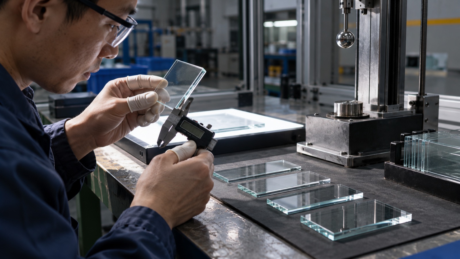
Industrial display cover glass has to be transparent, touch compatible, cleanable, printable, bondable, and strong enough for the enclosure. Those requirements pull in different directions. Thicker glass may improve stiffness and impact energy distribution, but it adds weight, increases the touch distance, and can create deeper bezel steps. A very hard surface may still fail from a damaged edge.
The right part is not “3 mm tempered glass.” It is a specified glass-and-enclosure system with defined loads, optical limits, and process controls.
Begin with hazards, not a favorite thickness
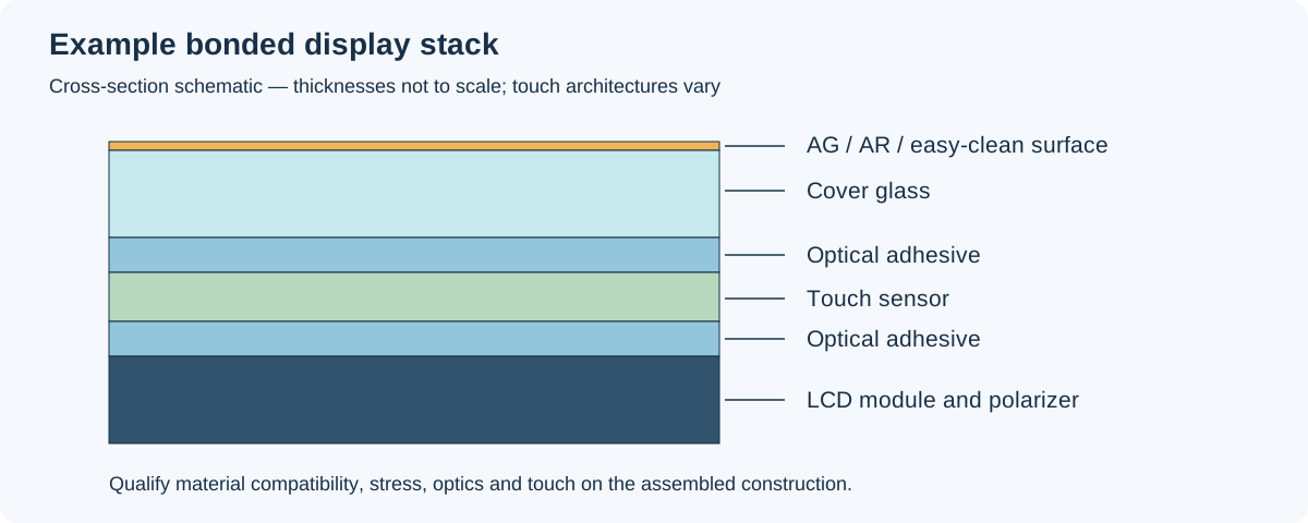
Example construction. Layer thicknesses and touch architecture must follow the released assembly drawing.
List how the product can actually be damaged:
- Finger and stylus use only.
- Tool impact or deliberate vandalism.
- Dropped handheld unit.
- Front-panel flex during button presses.
- Vibration and enclosure twist.
- Thermal shock, ice, or direct sun.
- Chemical cleaning and abrasive dust.
- Edge impact during assembly or service.
Then state whether failure means cosmetic scratching, loss of touch, glass fracture, fragment release, water ingress, or an unsafe sharp edge. A kiosk and a laboratory analyzer may use the same display size but need different cover structures.
Glass type and strengthening
Annealed soda-lime glass
Widely available and economical, with good optical clarity. It can be suitable where loads are modest and the enclosure provides strong support. Untreated thin glass has limited damage tolerance once surfaces or edges are flawed.
Thermally tempered glass
Heating and rapid cooling create surface compression. It is common for larger or thicker sheets and can provide a characteristic fragmentation behavior. Process capability, minimum thickness, hole/edge geometry, and optical distortion must be reviewed with the fabricator.
Chemically strengthened glass
Ion exchange places the surface into compression, making it attractive for thin cover lenses and complex industrial shapes. Corning explains that its ion-exchange process replaces smaller surface ions with larger ions to create compression in its cover-glass strengthening overview.
Strength is not a single material constant. Surface flaws, edge finish, compressive stress, depth of layer, part size, load rate, and support all affect fracture. Corning’s display-glass research also shows why handling damage matters: its study of display-panel damage resistance reports that processing flaws can sharply reduce the strength of otherwise strong glass.
Thickness changes the complete design
Thicker cover glass generally increases bending stiffness strongly, but thickness alone does not guarantee impact survival. Consider:
- Unsupported span and bezel support width.
- Adhesive modulus and thickness.
- Distance from cover glass to LCD.
- Impact tip shape and support conditions.
- Holes, notches, and corner radii.
- Edge restraint and assembly preload.
- PCAP controller tuning margin.
- Total product mass and center of gravity.
For touch, thicker glass reduces the capacitive signal from the finger. A controller may compensate with higher sensitivity, but that can reduce water and noise margin. Validate the final stack rather than approving glass and touch separately.
Edge quality often controls fracture
Glass is strong in compression and sensitive to tensile stress concentrated at flaws. Chipped, poorly ground, or exposed edges can dominate performance even when the front surface is pristine.
Specify:
- Cut method.
- Ground, seamed, polished, or chamfered edge.
- Minimum corner radius.
- Maximum chip dimensions and inspection lighting.
- Hole-to-edge and notch geometry.
- Protected handling and packaging.
- Whether the edge remains exposed in the product.
The enclosure should avoid point contact. Hard metal bosses, trapped particles, or over-tight fasteners can introduce localized stress. Use controlled support surfaces and account for tolerance stack-up.
Impact ratings belong to assemblies
A glass coupon that survives a ball drop does not prove an assembled HMI meets an impact requirement. Support, opening size, adhesive, bezel, LCD clearance, and mounting change the stress field.
Define the test with:
- Impact energy and striker geometry.
- Location, including center, corner, and near-edge points.
- Number of strikes.
- Product orientation and mounting.
- Temperature conditioning.
- Acceptance: no crack, retained fragments, continued touch/display function, ingress protection.
If the product claims an IK rating or another compliance level, test the complete representative enclosure to the applicable standard through a qualified lab. Do not translate a supplier’s raw-glass drop result into an enclosure rating.
Clarity is more than transmission
Uncoated clear glass can transmit most visible light, yet the finished stack may lose contrast because every refractive-index transition reflects some light. Evaluate:
- Luminous transmission.
- Specular reflectance.
- Haze and clarity.
- Color shift.
- Birefringence/stress pattern where polarized viewing matters.
- Surface waviness and optical distortion.
- AG sparkle at the intended pixel density.
Anti-reflection coatings reduce specular reflection; anti-glare treatments spread reflection over a wider angle. They are not interchangeable. Use anti-glare versus anti-reflection trade-offs to choose the mechanism that matches the environment.
Printed borders and windows need engineering limits
Black border ink hides adhesive, structure, and touch routing. It also creates a height step, can trap bubbles during lamination, and may absorb solar energy.
Specify:
- Ink system and cure process.
- Optical density and color.
- Printed-side orientation.
- Thickness and edge taper.
- Registration to active area and touch electrodes.
- Adhesion after chemical and environmental exposure.
- Compatibility with OCA/OCR and sealants.
- IR transmission if hidden sensors require it.
Measure cover temperature on black borders during sun-load testing. Local expansion and adhesive stress can differ from the clear window.
Optical bonding changes mechanical behavior
Bonding removes the air gap, reduces internal reflection, blocks condensation in the gap, and couples the cover mechanically to the display. It also transfers cover flex and thermal strain into the LCD stack.
The industrial display optical-bonding process should be evaluated for adhesive modulus, thickness, cure, rework, bubble control, and material compatibility. Very stiff bonding or poorly controlled flatness can produce LCD mura. Soft materials can relieve stress but may allow movement or edge pumping.
Maintain clearance between unbonded cover glass and the LCD under maximum expected deflection. “It does not touch at rest” is not enough.
Surface coatings and cleaning
Cover glass may combine:
- Anti-glare etch or coating.
- Anti-reflection multilayer coating.
- Oleophobic easy-clean top coat.
- Hard coating.
- Conductive or EMI shielding layer.
Confirm process order and compatibility. An oleophobic coating durability test should use the real cleaners, cloths, soils, and cycle count. Surface functionality can wear long before the glass loses structural strength.
A balanced prototype matrix
Do not prototype every possible stack. Choose samples that answer specific risks:
| Sample | Question it answers |
|---|---|
| Thin strengthened clear glass | Best touch/weight baseline |
| Thicker strengthened clear glass | Stiffness and impact benefit |
| Selected thickness with AG | Reflection versus sparkle/text clarity |
| Selected thickness with AR + oleophobic | Contrast, fingerprints, coating durability |
| Final printed and bonded stack | Production optical/mechanical interaction |
Use the same display, UI, touch firmware, and enclosure support while comparing optical treatments. Change one factor at a time.
Qualification should include production variation
Test samples from more than one glass and processing lot. Include minimum and maximum thickness, print step, adhesive thickness, and enclosure tolerance. Useful tests may include:
- Dimensional and cosmetic inspection.
- Four-point bend or supplier strength characterization.
- Product-level impact and drop.
- Thermal cycle and thermal shock.
- Damp heat and UV.
- Chemical and abrasion resistance.
- Touch performance with gloves and water.
- Optical measurement and outdoor readability.
- Vibration with post-test edge inspection.
After environmental exposure, inspect under both bright field and dark field. Small edge damage can be missed in ordinary room lighting.
Supplier drawing checklist
- Glass composition and strengthening process are identified.
- Nominal thickness and tolerance are stated.
- Compressive-stress/depth requirements are defined where relevant.
- Edge finish, corner radii, holes, and chip limits are dimensioned.
- Flatness, bow, and surface waviness limits are included.
- Print color, optical density, thickness, and registration are controlled.
- AG/AR/oleophobic sides are clearly marked.
- Optical, cosmetic, chemical, and abrasion criteria are measurable.
- Packaging prevents glass-to-glass contact and coating contamination.
- Lot traceability and change notification are required.
For a widescreen outdoor design, pair the final stack with a representative module such as the 7-inch high-brightness IPS panel and repeat impact, touch, optical, and thermal tests in the actual enclosure.
Cover glass is not selected by thickness or hardness alone. Begin with hazards and failure consequences, then design the substrate, strengthening, edges, support, coatings, print, bonding, and touch tuning as one stack. Test the finished assembly at tolerance corners. That is how a clear front window becomes a reliable part of an industrial product rather than its most exposed weakness.