Designing a Usable Backlight Dimming Curve for Day and Night
Build a usable LCD brightness curve with measured luminance, PWM and analog limits, smooth low-end steps, day/night targets, and repeatable validation.
The first ten positions on a brightness slider often reveal more about a display product than the last ten. If position one is still dazzling at night, or the screen jumps from black to clearly visible at position four, a high maximum nit rating does little to improve the experience.
A usable dimming curve connects user intent to measured luminance. It also respects the limits of the LED driver, panel, thermal design, and operating environment. That connection needs calibration; a percentage sent to a PWM peripheral is only a command.
Photograph: EEIM, CC BY-SA 3.0, via Wikimedia Commons. Resized and cropped; the adapted photo retains the same license. This is a real monitor scene, not a dimming comparison or a measured result.

Begin with the required luminance range
Specify a daytime target and a nighttime target in cd/m², then verify them in the finished product. Include viewing distance, UI content, front glass, reflections, and ambient lighting. A handheld terminal in a dim warehouse and an outdoor vehicle console need different floors and ceilings.
Do not infer the low end from the maximum specification. A module rated at high luminance may have a driver that cannot regulate smoothly at very low output. Conversely, a wide advertised dimming ratio may be measured under conditions that do not match the production load or PWM frequency.
Separate these requirements:
- Maximum sustained luminance at the allowed temperature.
- Minimum stable, nonzero luminance.
- Full-off behavior.
- Resolution of useful steps near minimum.
- Transition speed and startup behavior.
- Allowed color change, flicker, and noise.
The LCD luminance specification provides the measurement context. The dimming curve should be written against that optical output.
Measure the hardware transfer function
Sweep the brightness command from minimum to maximum while measuring screen luminance and input power after a repeatable settling period. Use more points at the low end, where dead zones and discontinuities are most visible. Repeat the sweep downward to detect hysteresis or mode changes.
Record panel revision, backlight current, driver configuration, PWM frequency, supply voltage, temperature, and pattern. The same nominal command can produce different output after a driver register change.
The result is a transfer function:
Hardware command → measured screen luminance
Your firmware needs the inverse relationship: for a requested luminance, which command should it send? A calibrated lookup table is often easier to maintain than a single equation that fits poorly near minimum.
Know what the PWM input actually controls
Some drivers switch LED current on and off with the PWM signal. Others filter the PWM input and use it to set a continuous analog current. A hybrid implementation may change behavior across its range.
These methods have different low-end, color, acoustic, and timing characteristics. TI’s PWM-to-analog LED dimming application note explains why a PWM command does not necessarily mean the LED current itself is pulsed at that frequency.
Check the waveform at the backlight current path with an appropriate measurement method. Looking only at the MCU output proves that the command exists, not that the driver reproduces it.
Minimum pulse width can set the floor
For direct PWM dimming, the on-time is:
Ton = duty cycle / PWM frequency
As an illustrative calculation, 0.1% duty at 20 kHz gives 50 ns of commanded on-time. If a particular driver requires 2 µs to establish a useful regulated pulse, that setting cannot produce the intended proportional output. The actual minimum depends on the device and circuit.
TI’s switched-mode LED dimming discussion connects PWM dimming range with driver response and minimum on-time. Use the target driver’s limits, then confirm on the bench.
Increasing PWM frequency can reduce some visible artifacts while shortening the available on-time at low duty. The frequency choice must also consider camera interaction, EMI, acoustics, and the user’s task. A single frequency threshold does not guarantee freedom from all temporal artifacts.
Shape the user curve independently
Equal electrical steps rarely feel like equal brightness steps over a wide range. A practical starting point is a nonlinear mapping from slider position to target luminance:
x = slider position normalized to 0…1
Ltarget = Lmin + (Lmax − Lmin) × x^g
An exponent greater than one allocates more slider travel to low luminance. The exponent is a tuning parameter, not a universal property of vision. Compare it with a logarithmic mapping or a hand-tuned piecewise curve using the actual UI.
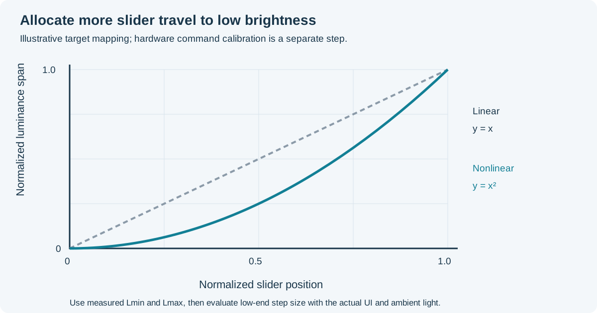
Illustrative curves, not measured panel output. Calibrate hardware commands separately.
Once the desired target curve is chosen, map each target through the measured hardware table. This avoids assuming LED output is exactly proportional to a command across temperature and operating modes.
Treat full off as a separate state
The lowest useful brightness and backlight off need distinct definitions. Near zero, drivers may show leakage, pulse skipping, or inconsistent startup. Use the specified enable sequence when a real off state is required.
Keep the panel’s logic and reset sequencing independent from brightness changes unless the product intentionally enters a deeper sleep mode. Re-enabling the backlight before valid video can create a bright flash. The LCD backlight enable and shutdown sequence belongs in the same validation plan.
Day and night modes may need different curves
One curve spanning an extreme range can make manual adjustment awkward. A night mode can offer finer control near the bottom, while a day mode focuses on a higher range. If modes overlap, switching between them should preserve reasonable perceived brightness rather than jumping abruptly.
Account for the image as well as the backlight. A dark UI reduces bright area, but small white icons may remain uncomfortable. Reducing RGB values while leaving the backlight at full power can also waste energy and compress useful tonal detail.
Validate the UI and backlight together with warning colors, small text, full-screen dialogs, boot logos, and recovery screens. A well-tuned normal screen is insufficient if an error dialog appears at full white overnight.
Smooth changes in luminance, not just commands
A linear ramp in PWM count may pass through the low end too quickly. Ramp in the target-luminance domain or in the chosen perceptual control domain, then convert each step through the calibration table.
Use elapsed time rather than assuming a perfectly constant task rate. Define behavior when a new request arrives mid-ramp. Temperature limiting and user override should interrupt the transition predictably.
For automatic brightness, coordinate the output ramp with ambient light sensor filtering and hysteresis. Otherwise, two independent filters can make the response unexpectedly slow.
Validate across conditions and production units
| Check | Why it matters |
|---|---|
| Low-end upward/downward sweep | Dead zones, jumps, repeatability |
| Cold and hot operation | Driver regulation and LED-output change |
| Minimum and maximum supply | Startup, dropout, pulse behavior |
| Representative cameras | Banding or exposure interaction |
| Quiet environment | Inductor or ceramic-capacitor noise |
| Touch active during dimming | Coupled interference |
| Suspend, resume, and reboot | Flashes and restored state |
| Multiple panel lots | Calibration and tolerance margin |
Use a photodiode and oscilloscope when temporal behavior matters. A handheld luminance meter may average pulses and hide modulation. Fixed-exposure photographs help document appearance, but they do not replace waveform measurements.
Release the curve, hardware calibration, driver settings, and test conditions together. If a backlight LED, driver, or current-setting resistor changes, repeat the low-end checks. The useful result is a slider whose behavior remains predictable from the first production unit to the replacement module years later.