Ambient Light Sensors for Automatic Display Brightness Control
Design reliable LCD auto brightness with an ambient light sensor: placement, dark-glass calibration, filtering, hysteresis, display-light rejection, and fault handling.
Automatic brightness is easy to demonstrate: shine a lamp at the sensor and the screen gets brighter. Making it comfortable in a finished product takes more work. A user’s hand casts a shadow, a ceiling light flickers, the black lens attenuates the signal, and the display itself may illuminate the sensor.
A reliable design treats the ambient light sensor as one input to a controlled luminance system. The optical path, firmware, backlight hardware, and user override all need defined behavior.
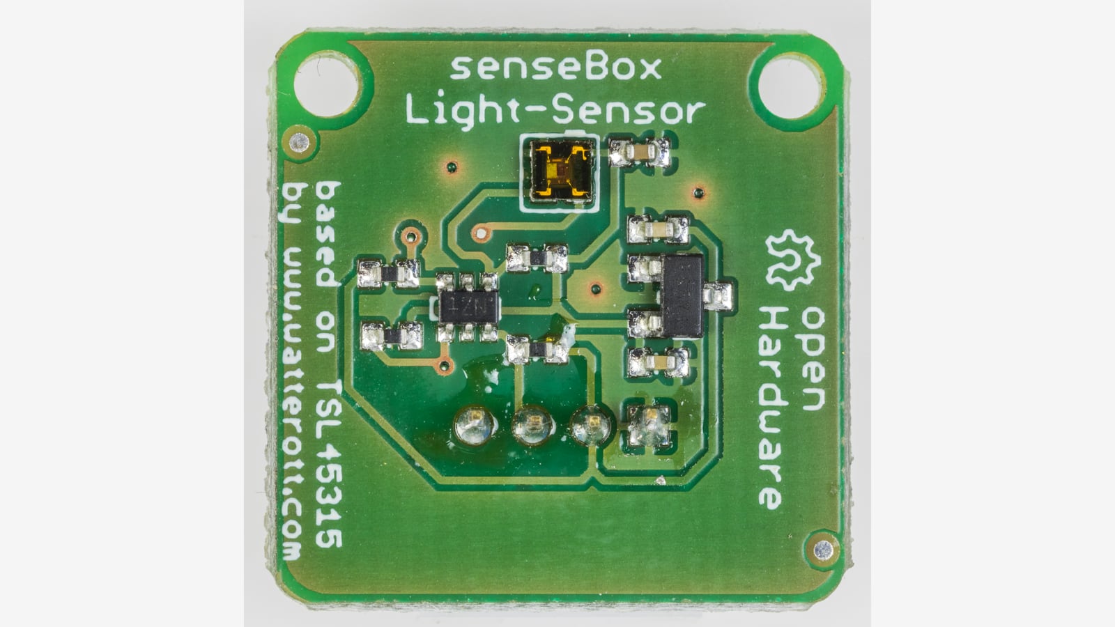
Photograph: © Raimond Spekking / CC BY-SA 4.0, via Wikimedia Commons. Resized and padded to a wide format; the adapted photo remains under the same license. The pictured sensor is an example, not a specified component for this design.

Define the controlled output in nits
Lux measures light arriving at a surface. Nits describe display luminance toward a viewer. An ALS provides the first quantity, while the backlight controller influences the second. There is no universal conversion between them.
Write the intended behavior as a relationship between ambient conditions and target screen luminance, then translate that target into a hardware command using measured data. For example, a sheltered industrial terminal may need one nighttime floor and a different daylight ceiling from an exposed outdoor kiosk.
Use the lux and display-luminance measurement method to keep the two quantities separate during calibration.
Select for the complete optical path
An ALS should have a useful response over the product’s expected illumination range, adequate low-light resolution, suitable conversion time, and predictable spectral behavior. Human-eye-like spectral response and infrared rejection help avoid large differences between readings under different lamp types.
TI’s OPT3001 ambient light sensor documentation illustrates these selection parameters, including spectral response, measurement range, integration, and digital readout. A component example does not establish the final product’s accuracy: lens transmission and mechanical placement still need calibration.
Check saturation explicitly. A sensor that reaches full scale in strong sunlight cannot distinguish brighter conditions beyond that point. Decide whether the correct response is simply the approved daylight maximum or whether a wider-range sensor is necessary.
Position is often the largest error source
Place the sensor where it sees light representative of the display’s environment. Keep it away from bezel shadows, recessed corners, status LEDs, and internal light leaks. A sensor on a side wall may see a very different illumination from a tilted display face.
Review its angular field of view with the actual aperture, adhesive, and glass. A narrow opening can block oblique light even when it looks clear from the front. If the product rotates, evaluate every supported orientation.
Do not optimize placement using the bare board alone. Build the lens, black mask, gasket, and sensor cavity. Then measure the response under diffuse light and directional light from several angles.
Dark glass needs source and tolerance checks
Black windows are convenient for hiding sensors, but their transmission can vary with wavelength, thickness, ink, and coating. A single gain correction measured under one white LED may not remain accurate under sunlight or another lamp spectrum.
Compare reference illuminance with raw sensor readings using several representative sources and the final window. Include samples across production tolerances. Store calibration coefficients with the optical-stack revision rather than letting them become an unexplained constant in firmware.
TI’s display backlight control application brief discusses the value of spectral matching and IR rejection, including sensors mounted behind dark glass. The practical follow-up is to verify the complete assembly under the light sources the product will encounter.
Prevent the display from controlling its own sensor
A sensor can pick up light from the LCD or from internal reflections. The feedback loop then becomes:
Display brightens → sensor reads more light → display brightens again
Use opaque barriers and a controlled sensor cavity first. Test with the room lighting fixed while alternating black, white, and high-brightness UI content. If the ALS reading changes materially with displayed content, the mechanical design or compensation strategy needs attention.
Software subtraction can work only when the coupling is characterized and stable. It becomes fragile if leakage changes with lens tolerances, assembly gaps, temperature, or content distribution.
Separate filtering, mapping, and transitions
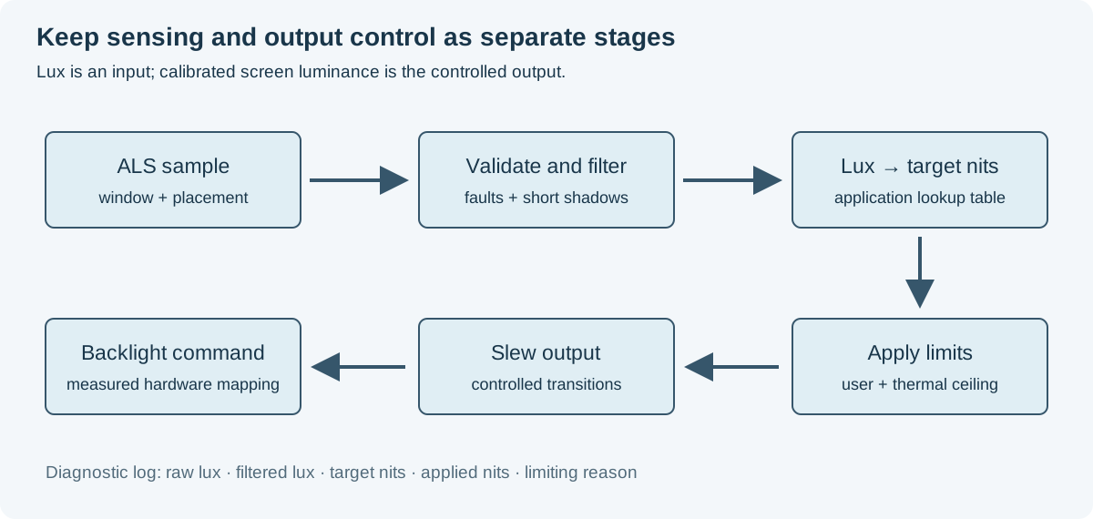
Use distinct stages so each behavior can be tuned and tested independently:
- Validate the sample and detect saturation or communication errors.
- Filter short variations in the ambient reading.
- Apply a calibrated lux-to-luminance lookup table.
- Apply user preference and thermal or electrical limits.
- Slew the output toward the target.
- Convert target luminance to the released backlight command.
This structure makes it easier to explain why the display is at a particular brightness. Log raw lux, filtered lux, target nits, applied nits, and the limiting reason during development.
Filtering should reject shadows without ignoring real changes
A moving hand should not make the screen pulse. A transition from shade into sunlight should not leave it unreadable for several seconds. Often it helps to use different response times for brightening and dimming, selected from usability tests.
A simple exponential filter can be sufficient:
filtered = previous + alpha × (sample − previous)
Choose alpha with the actual sample interval in mind. If sampling changes from 10 Hz to 2 Hz, reusing the same alpha changes the time response. A time-constant formulation avoids that accidental dependency.
Hysteresis and a dead band reduce hunting
Near a boundary between two brightness levels, small measurement changes can cause repeated switching. Use separate up/down thresholds or a dead band around the current target. Add a persistence requirement if brief shadows remain a problem.
If the output curve is continuous, quantization in the sensor or PWM command can still create visible steps. Inspect the low-light end carefully.
Keep the user in the loop
Provide a way to adjust brightness preference without forcing the user to disable automatic control entirely. A limited offset or multiplier can work if the resulting output still respects the validated night floor and daytime ceiling.
Store preference separately from calibration. After a software update, a new calibration should not erase the user’s choice, and a user reset should not replace factory optical coefficients.
Define faults before field use
Decide what happens if the sensor is absent, stuck, saturated, covered, or returning invalid data. A zero reading could mean a dark room, an obstructed aperture, or a failed device. Do not interpret every zero as a command for minimum brightness.
Useful protections include range checks, stale-data detection, a controlled startup default, and a manual recovery path. For products with critical information, the fallback luminance must support the task under the specified fault conditions.
Validate the transitions, not only steady values
| Test | Observe |
|---|---|
| Dark room to bright light | Time to useful readability, overshoot |
| Bright light to dark room | Comfort, dimming delay, minimum output |
| Hand over aperture | Short-shadow rejection and recovery |
| Black/white content at fixed light | Display-to-sensor coupling |
| Multiple lamp spectra | Calibration consistency |
| Maximum panel temperature | Thermal limit behavior and logging |
| Bus fault or sensor reset | Fallback and recovery |
Run this matrix with the final enclosure and firmware. The day and night backlight dimming curve defines the output side, while high-brightness backlight thermal checks establish the available ceiling.
The best auto-brightness behavior is usually uneventful. The screen reaches a useful level, small disturbances do not attract attention, and the user can understand and override the result. Achieving that requires a measured optical path and a transparent control policy more than a complicated algorithm.